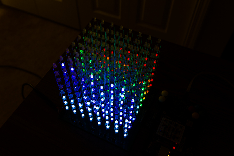
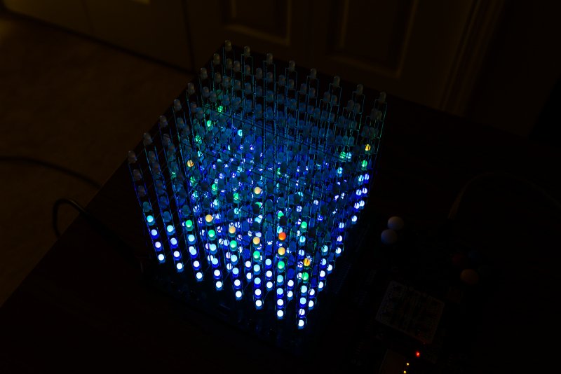
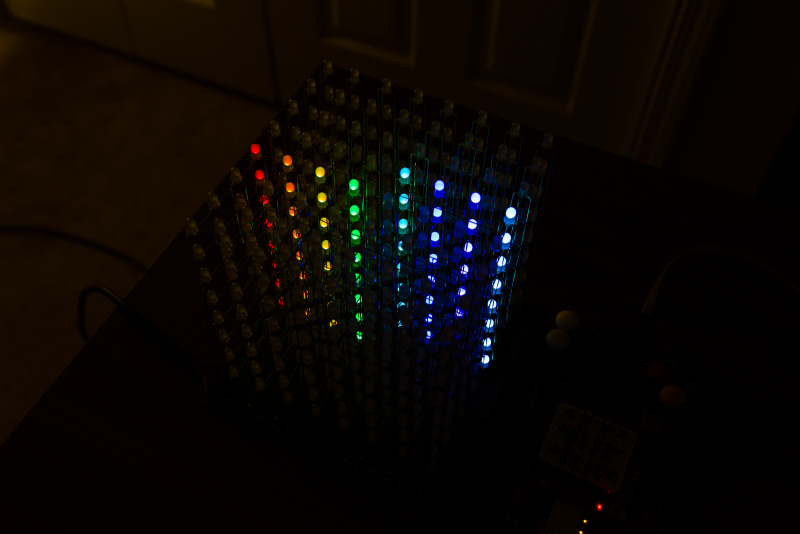
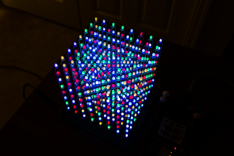
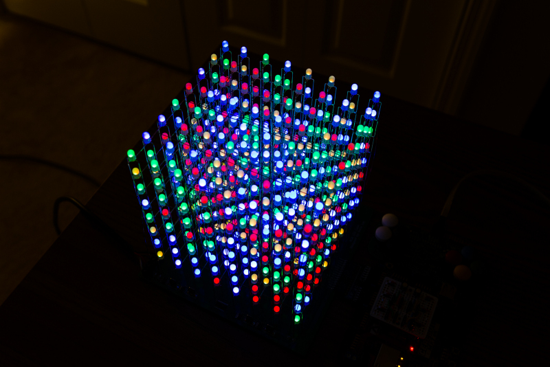
The original post for the LED cube can be found here
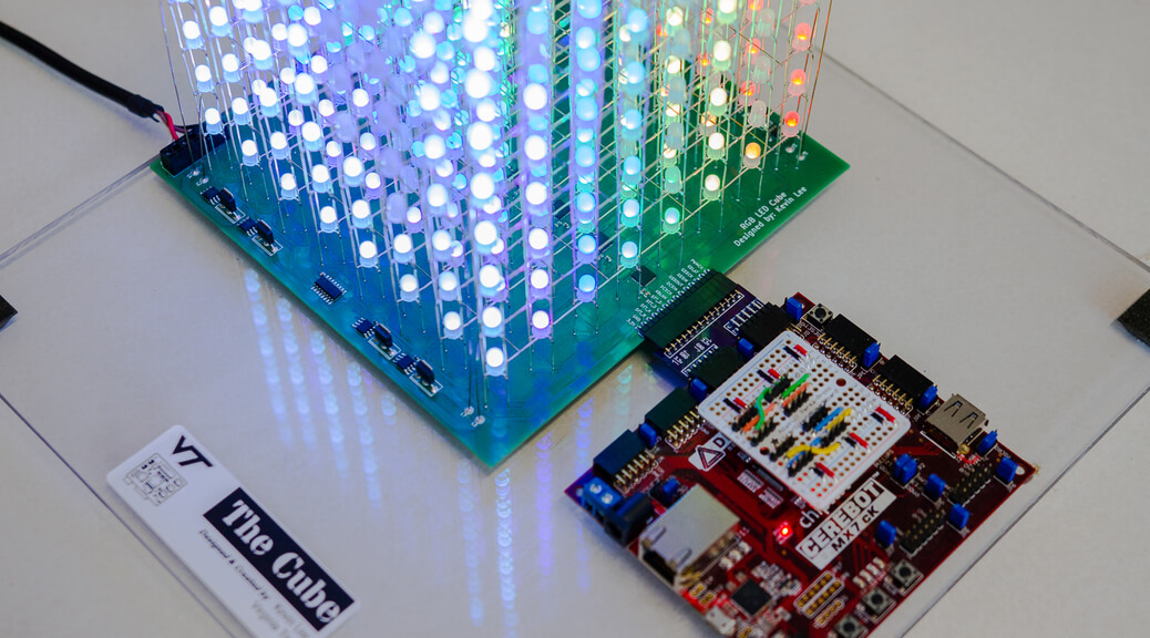
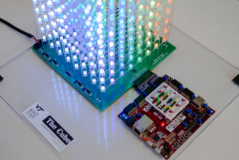
While the LED cube itself is pretty much finished, I recently had a chance to add a few new features and improvements to both the code and hardware. The main hardware improvement so far is a cube-to-Cerebot adapter PCB that replaces the interconnecting cable between the processor board and cube PCB. On the software side, I implemented a custom Ethernet driver that allows a user to read and process raw Ethernet packets. Using this driver, I added a new API that allows any external computer capable of writing raw Ethernet packets to control the cube. I also wrote the corresponding Python API that runs on any Linux machine with root.
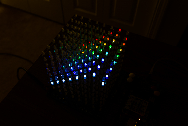
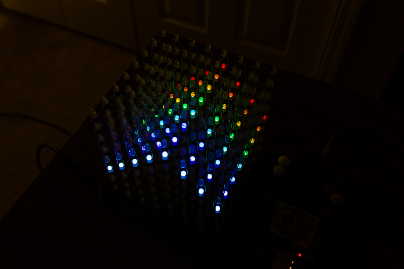
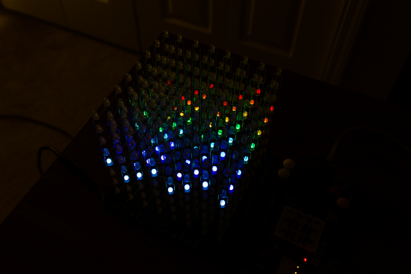
New Animations!
Hardware Updates
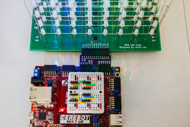
Cube-To-Cerebot Adapter
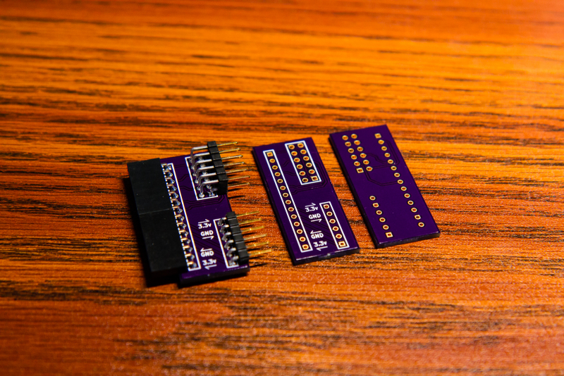
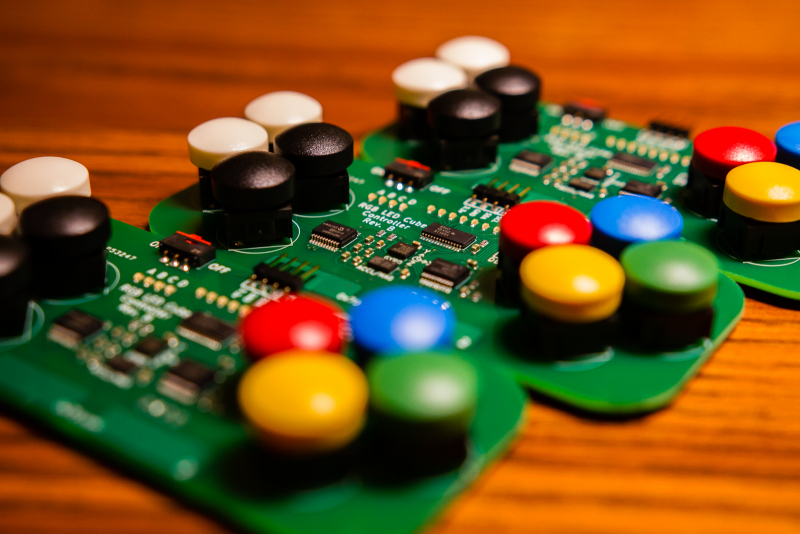
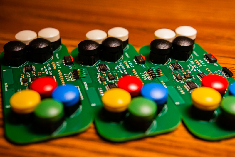
One of the main problems that I had with the cube was that the data signals from the Cerebot was getting corrupted after a small period of time. On startup, the cube would run fine for anywhere between 15 minutes to an hour before some of the LEDs started showing signs of corruption. These errors usually manifested themselves as the wrong color or brightness during an animation, and a reset of the Cerebot board was required to restore the cube to a pristine state. I theorized that the interconnecting cable between the Cerebot board and the cube PCB was likely the source of these errors. Therefore, to fix the issue, I designed and ordered from OSHPark a few custom adapter boards that connect the 14-pin cube interface to two of the PMods on the Cerebot board. I have yet to extensively test this new connector, but so far it seems to have fixed the problem.
I2C Expander Breakout
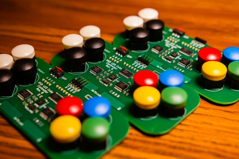
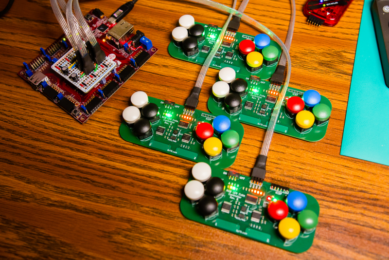
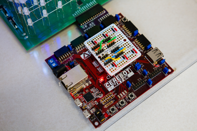
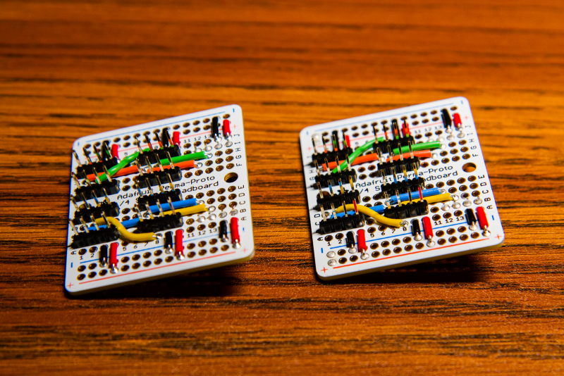
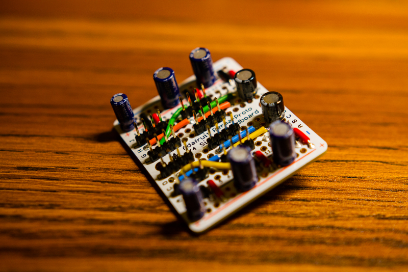
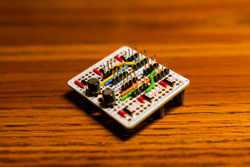
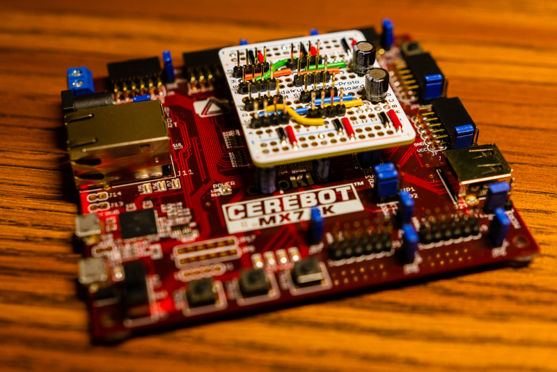
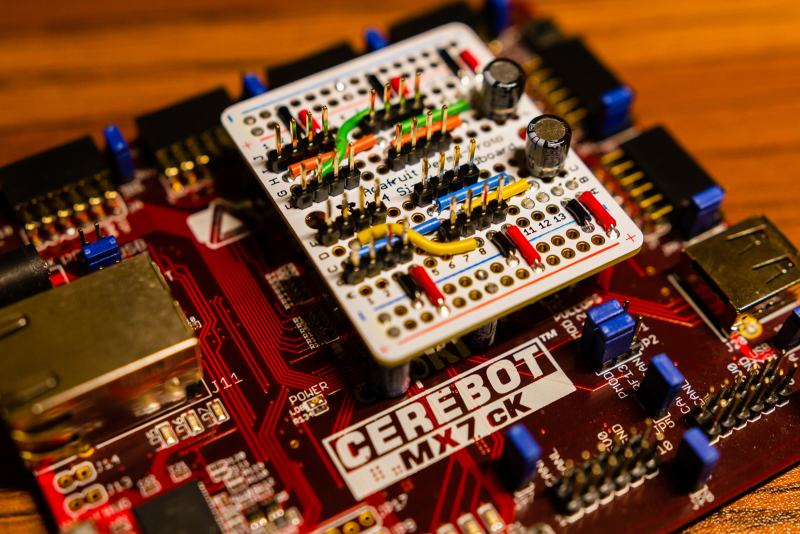
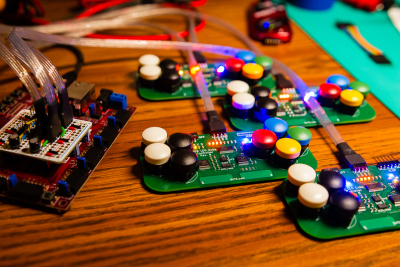
Another hardware update that I made was with the I2C expander boards that I put together awhile back. The issue was that there was no clear distinction between which connectors were associated with I2C1 and I2C2. To fix this, I simply changed the wiring color of half the board. I also had to make a second board so that both of my LED cubes would have one. If I find the time, I may go ahead and design a custom PCB with proper silkscreen labeling.
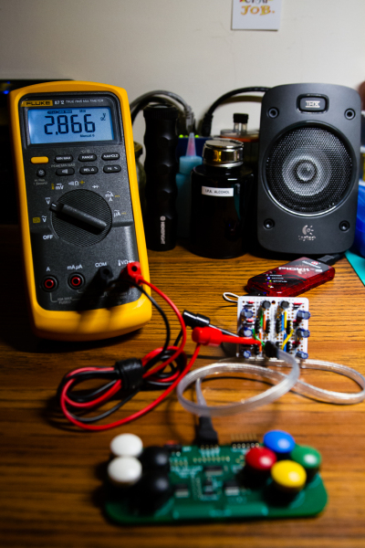
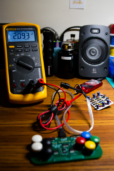
Another issue that cropped up with the controllers was how it was resetting the Cerebot board whenever it was plugged in or powered on. With my new Fluke 87-V, I was able to test the 3.3v rail and determined that the voltage dropped below the brownout voltage of 2.3v. Normally a multimeter wouldn’t be able to measure transients of such short duration, but the 87-V has a feature where it can measure extremes down to 250us. To remedy this voltage drop issue, I added an overkill amount of bypass capacitors to provide some extra stability.
Software Updates
Adding Ethernet Support
Originally I was going to leave the Ethernet interface for someone else to implement, but my graduate lab wanted to use my cube as a front-end visualizer for some of the demos that they’re running. As none of my existing APIs were fast enough to accommodate what they wanted to do, I decided to write a new API that utilizes the 100Mbps Ethernet interface. Since I didn’t want to use the TCP/IP library from Digilent or the similar library from Microchip (too much overhead), I decided to write my own driver that would interface to the LAN8720 chip on the Cerebot board. Writing this driver however, took a bit longer than expected due to some missing information in the PIC32 reference manual. After throwing a few days at it though, I managed to figure it out.
The difference between my driver and Digilent/Microchip’s driver lies in how the network packets are processed. Their libraries has quite a bit of overhead due to a full implementation of TCP/IP with DHCP, DNS, socket support etc. In contrast, my driver reads and writes raw Ethernet frames to and from the wire. While there are certainly benefits from using Microchip’s library, I tend to favor the speed and simplicity of my implementation.
In addition to the PIC32 side of the code, I also wrote a python API that provides a number of functions for controlling the cube. By writing the wrappers for the raw frame generation, I’m hoping that I made the interface easy enough for a programming beginner to pick up and use without too much effort. A snipping of the python code is show below:
|
1 2 3 4 5 6 7 8 9 10 11 12 13 14 15 16 17 18 19 20 21 22 23 24 25 26 27 28 29 30 31 32 33 34 35 36 37 38 39 40 41 42 43 44 45 46 47 48 49 50 51 52 53 |
# Set the address of the Cerebot board dst_addr = '00183E00D7EB'.decode('hex') # Open a socket on the eth0 sock = socket.socket(socket.AF_PACKET, socket.SOCK_RAW) sock.bind(("eth0", 0x1)) # Acquire MAC address of local machine if_name, if_proto, pkt_type, hw_type, hw_addr = sock.getsockname() # Create and initialize the frame buffer frame_buffer_size = 1536 frame_buffer = [0] * frame_buffer_size def cube_init(): '''Sets the cube into ethernet mode.''' # Generate and send the frame txFrame = struct.pack("!6s6sH", dst_addr, hw_addr, 1) txOpcode = "01".decode('hex') sock.send(txFrame + txOpcode) # Wait a few seconds for the cube to reset itself time.sleep(6) def cube_reset(): '''Resets the cube into idle mode.''' # Generate and send the frame txFrame = struct.pack("!6s6sH", dst_addr, hw_addr, 1) txOpcode = "02".decode('hex') sock.send(txFrame + txOpcode) def cube_clear(): '''Clear the cube's internal buffer.''' # Generate and send the frame txFrame = struct.pack("!6s6sH", dst_addr, hw_addr, 1) txOpcode = "0A".decode('hex') sock.send(txFrame + txOpcode) def cube_update_pixel(x, y, z, r, g, b): '''Set a specific pixel on the cube.''' txFrame = struct.pack("!6s6sH", dst_addr, hw_addr, 7) txOpcode = "11".decode('hex') frame = [x, y, z, r, g, b] txData = ''.join("%02x" % (x) for x in frame) sock.send(txFrame + txOpcode + txData.decode('hex')) def cube_update(): '''Updates the cube with the current frame buffer. The buffer is sent in three frames, one for each color channel.''' txFrame = struct.pack("!6s6sH", dst_addr, hw_addr, 514) txOpcode = "12".decode('hex') for c in range(3): txColorCh = "%02x" % c txData = ''.join( ["%02x" % (x) for x in frame_buffer[c::3]]) payload = txFrame + txOpcode + txColorCh.decode('hex') + txData.decode('hex') sock.send(payload) |
To make it even easier for beginners, I even have a sample main function that generates a basic expanding sphere animation. I plan on eventually expanding the python API to the point where it covers all the internal cube control functions (and perhaps animations).
|
1 2 3 4 5 6 7 8 9 10 11 12 13 14 15 16 17 18 19 20 |
from cube import * import animations from time import sleep if __name__ == '__main__': # ----- Begin animations ----- cube_clear() cube_update_text("CCM LAB ", 0xFF, 0xFF, 0xFF, 100) # Loop an expanding sphere animation print "Looping animations...\n" while(1): for i in range(9): cube_clear() cube_update_sphere(i, 0xFF, 0x00, 0x00) sleep(0.1) # ----- End Animations ----- |
