Design files for this project can be found here (firmware) and here (3D models)
Update 12/18/2020 – Updated design to revision E3
Update 2/1/2021 – Added notes on cooling performance and upgrades
Earlier this year I bought and assembled my own Prusa i3 mk3s as a quick way to iterate on various mechanical projects in the comfort of my apartment. There are plenty of reviews online for this model so I won’t be providing my own review here. I will however, say that this printer has vastly exceeded my expectations for the price. The small list of modifications that I have made to this printer so far include:
- Replacing the extruder head with a Bondtech Upgrade Kit for more consistent prints.
- Replacing the hotend components with a 50W heater, PT100 w/ amplifier, titanium heat break, and copper block to support high temperature filaments.
- Replaced the hotend unit with TriangleLab’s Dragon hotend.
- Installing the Bear X Extruder with the Bondtech X Carriage for the better belt tensioning mechanism.
After replacing the above components, I still encountered issues with uneven cooling on bridges and overhangs. This prompted me to try my hand at designing a better cooling shroud that evenly cools from all sides.


Revision A
The design that I eventually settled upon was to use brass tubing for directing air to the nozzle and two centrifugal fans to evenly pressurize the airflow chamber for even airflow among all the airflow ducts. The brass nozzles were used to prevent the plastic shroud from melting from being in close proximity to the heater block, which was a concern even with a silicone sock installed. The metal ducts will still conduct heat from the heater block to the plastic shroud however, albeit slowly. To remedy this, firmware modifications were necessary to ensure that a minimum amount of airflow (20% fan speed) is always enabled whenever the hotend is on.


Revision B
- Adding copper tape for some additional heat dissipation so that less airflow (10% fan speed) is required to prevent the plastic from melting. High thermal conductivity epoxy was used to connect the brass ducts to the copper tape.
- The plastic shroud design was modified to avoid collision with the Z lead screw with homing.
- The airflow ducts were modified at the tips to angle the airflow downwards instead of straight.
- The silicone sock was changed to a different version that doesn’t get damaged as easily.


Revision C
- Add a third mounting point on the back to keep the shroud from sagging.
- Angle the airflow ducts slightly off from the nozzle tip to create a ‘tornado’ effect that pulls in more air from the surrounding. This didn’t work as it resulted in very inconsistent extrusions and poor print quality when bridging.


Revision D
- Printed the shroud with Colorfabb’s HT filament (rated for 100°C).
- Added kapton tape for additional thermal insulation between the airflow ducts and the heater block.


Revision E1
While the previous revision worked, the metal ducts had a tendency to conduct heat to the shroud over time. This eventually caused the shroud plastic to soften and lower the ducts, which then introduced a risk of collision with the print. This is an inherent problem with having parts close to the hotend that can reach upwards of 300ºC
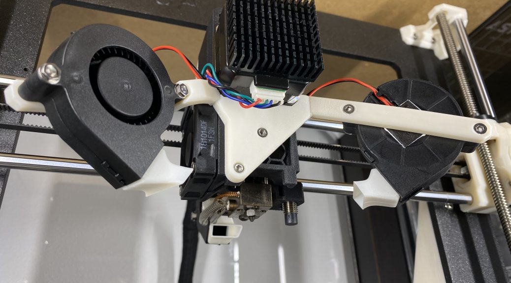
Instead of building on the concept of redirecting air via a shroud, I decided to take a entirely different approach: rather than feed air into a shroud from the front, would it be possible to point the radial fans directly at the hotend from all directions? It turns out that this is possible, but requires quite a few changes:
- The stock E3Dv6 hotend doesn’t have enough clearance on the bottom for good airflow, so I had to replace it with a Volcano hotend instead. As far as drawbacks go, this has the effect of slightly reducing the maximum printable Z volume as well as slightly increasing filament stringing. The stringing isn’t nearly as much of a problem since it can be reduced by slightly increasing the retraction distance and using dry filament.
- The rear fan mount collides with the stock frame at the top when calibrating the Z axis. I tried a few different variation for mounting the rear fan, but couldn’t come up with a way that was both structurally sound and didn’t interfere with the frame. I ended up having to modify the top Z-axis rod mounts to stop the travel before the carriage collides with the frame, which resulted in another 14mm reduction of the printable Z volume.
- Three identical radial fans are required for even cooling from all directions.
- Fan speeds needs to be reduced as even a 50W heater cartridge can only reach a maximum of 247ºC at 100% fan speed. Without a silicone sock, hotend temperature can also drop by up to 14ºC when the fan turns on.
- Firmware changes are required to support the smaller print volume: Z_MAX_POS is reduced from 204 to 184 and X_MAX_POS is reduced from 255 to 247.
The resulting setup actually works extremely well, with the printer being quieter overall due to the lower fan speeds required to achieve the same amount of airflow. Access to the nozzle is also significantly easier as there is nothing in the vicinity of the hotend except for the PINDA probe.


Revision E2
After a few hundred hours of experience with the previous revision, I found that the volcano hotend exhibited too much oozing when printing soft (eg. TPU) filaments. To remedy this, I decided to switch back to the regular E3Dv6 hotend that has a smaller melt zone. Naturally, an update to the design is needed to account for the height difference between the two hotends.
As the fans were moved to a higher position in this revision, the mounting arms for the front fans were redesigned to allow the individual arms to be printed flat and independently from the center mounting piece. Two 10mm M2.5 screws and nuts were used to assemble the three pieces.
One of my annoyances with the E3Dv6 hotend was that the entire hotend unit could rotate even after being mounted on the carriage. This made nozzle changes extremely tedious, with the user having to grip the hotend block with one wrench while simultaneously removing the nozzle with a second wrench. The Mosquito hotend fixes this problem, but would replace an expensive carriage replacement to use it as has a different mounting footprint than the E3Dv6. Instead, I ended up switching to TriangleLab’s Dragon hotend that is designed in a similar way to lock the hotend in place while also being backwards compatible with the E3Dv6 design.
To mount the Dragon hotend in such a way that it is fixed in place, I designed my own adapter mount for the Bondtech’s MK3S Extruder unit that I have installed on my printer. One point to note is that the heatsink for the Dragon hotend gets much warmer than the E3Dv6 design, so the adapter should be printed out of temperature resistant (eg. polycarbonate) material.


Revision E3
For this revision, nozzle ducts was added to improve the shaping of airflow. The idea here was to direct the air along the horizontal plane rather than the vertical plane so that air flows over the printed part instead of cooling the hotend block.
In addition to the fan ducts, I also reworked the left arm such that the mounting arm sits behind the fan rather than in front of it. This increases airflow a bit as the inlet was previously blocked by the arm. Vibration of the fan is also slightly reduced, which should increase the fan’s lifespan by a bit.
Unsurprisingly, cheap off-the-shelf radial (blower/centrifugal) fans are often lacking on the quality front, as the four-pack of sleeve-bearing ball-bearing fans that I bought rapidly deteriorated over the course of a few hundred hours of printing. Instead of replacing the fans to fix the rattling, I discovered that the rattling noise issue can actually be fixed by removing the rear sticker and dropping in some lubricating oil while fans are on.


Notes on Cooling Performance
One of the drawbacks (?) to this triple fan setup is that the cooling rate of the hotend is very likely going to exceed what the hotend itself is capable of sustaining. My testing shows that when running in a 70°C enclosure, a 50W heater cartridge was unable to maintain a hotend temperature of 280°C unless the fans are running at less than 70% duty cycle. To address this, I upgraded to a 60W heater cartridge and also decided to swap out the PT100 w/ amplifier for an AD8495 with a T-K500 thermocoupler while I was at it.
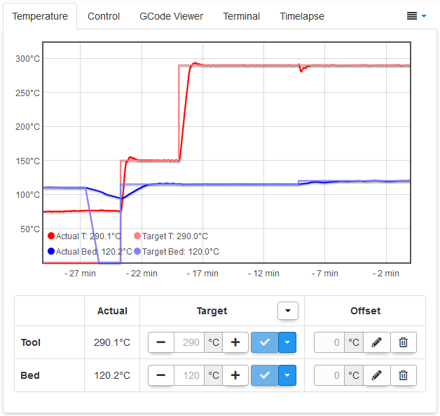
With the original PT100 amplifier setup, I was seeing a hotend output temperature of roughly ±0.6°C at 280°C with a 50W cartridge and 70% duty cycle fan. With the AD8495 properly wired up, I get an output temperature of ±0.2°C at 280°C with a 60W cartridge and 100% duty cycle fan. Pretty decent improvement if you ask me. For reference, P16.42 I1.47 D45.79 are the PID values that I ended up with after calibration.
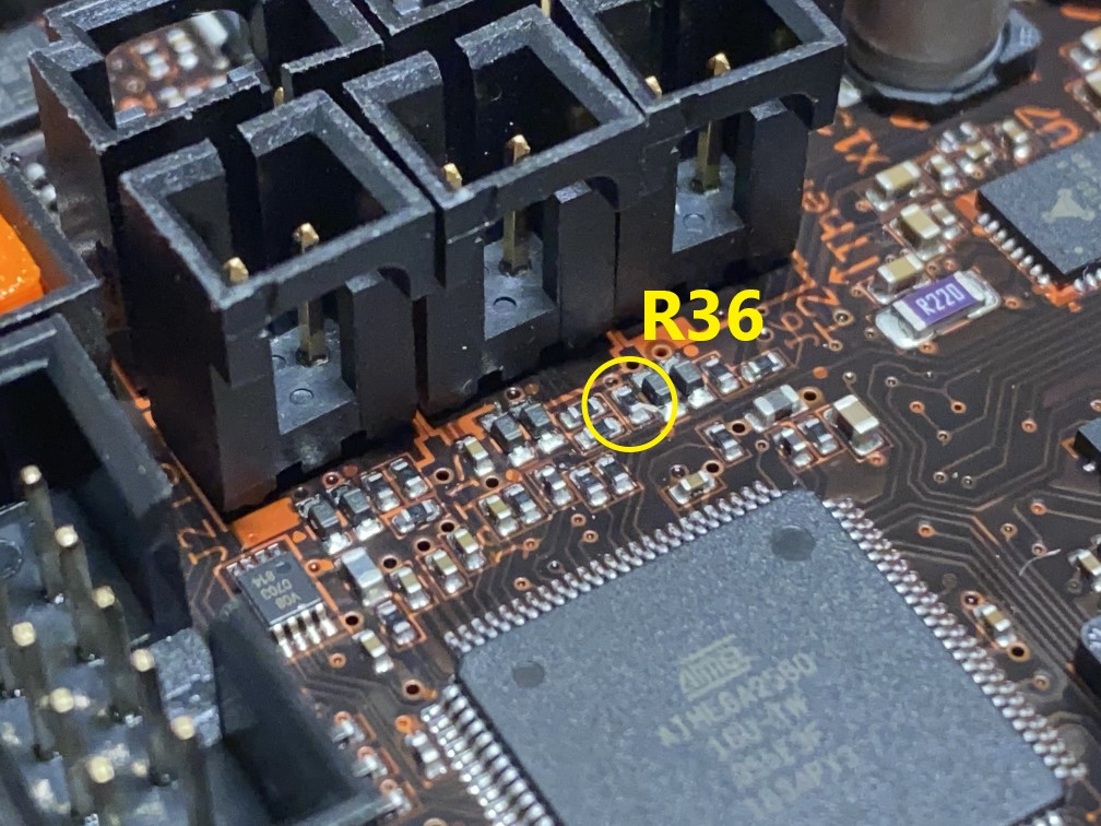
Adding support for the AD8495 on the Prusa’s Einsy Rambo board was a bit of a hassle though, as I had to remove the 4.7kΩ pull-up resistor on temperature input pin. To keep some semblance of backwards compatibility, I only removed this on the T1 input (R36) and not T0 (R31) where the hotend temperature probe originally connects to. The Einsy Rambo schematic provides more detail on how these input pins are hooked up.
In addition to the hardware modification, the firmware also took some changes to add support for the AD8495. While Prusa’s firmware natively supports using a PT100 alongside the 4.7kΩ pull-up resistor by connecting it to the T0 temperature input (J2) and a 5V source (J7), it wasn’t particularly accurate from my experience as I had to make some tweaks to the temperature look-up table. The AD8495 is much more straightforward as there is a linear relationship between the two.
Note that there are actually two different commercial variations of the AD8495 breakout board: one with a 1.25V voltage reference source (eg. Adafruit’s board) and one without (eg. TriangleLab’s board). My firmware changes target the latter, but it should be a small firmware addition to bias the input value. On both variations of the breakout board, you will also notice that there are two ground pins on the connection to the Einsy board. Both grounds from the temperature signal input (J3) and 5V reference (J7) must be connected, otherwise you will see an erroneous 4°C increase in the reported temperature when the fans turn on due to a small voltage drop on the 5V rail.