The latest code base for this project can be found here
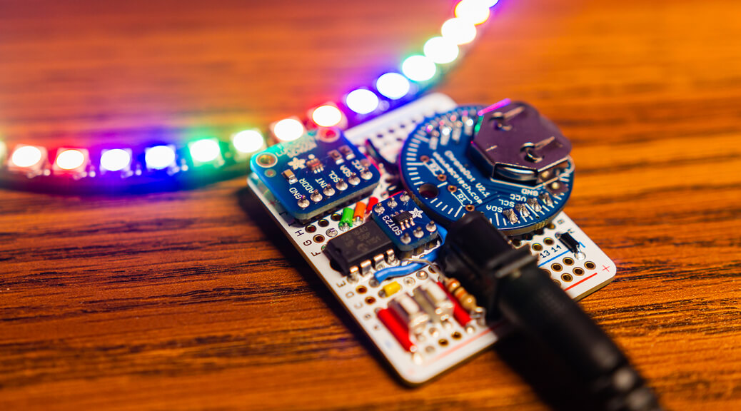
Here’s a quick weekend project that I did a week or so back. I decided to put together a standalone wall clock using Adafruit’s 60 NeoPixel ring, a ChronoDot real-time clock (RTC), TSL2561 light sensor, and a PIC12F1840 to tie everything together. The hardware was pretty straightforward, but the interesting part about this project was really with the one-wire protocol used to control the NeoPixels.

")
")
Custom NeoPixel Driver
As I typically use Microchip’s PIC microcontrollers in my projects, I had to write my own driver for one-wire protocol used by the NeoPixels. This protocol is extremely reliant on precise timings, so in order to achieve these timings most drivers use a tight assembly loop for generating the signal. As I wanted to avoid writing anything in assembly, I decided to instead use the Capture/Compare/PWM (CCP) peripheral on the PIC12F1840 to achieve the same result.


")
")
")


![]()
![]()
Here is the initialization sequence for the CCP peripheral:
|
1 2 3 4 5 6 7 8 9 10 11 12 13 14 15 16 17 18 19 20 |
// Output pin initially blocked NEOPIXEL_TRIS = 1; /* Initialize PWM module */ PR2 = 0x09; // 1.25us @ 32MHz CCP1CONbits.P1M = 0b00; // Single output, P1A modulated only CCP1CONbits.CCP1M = 0b1100; // PWM mode, P1A active-high, P1B active-high // Idle the output till width is specified CCPR1L = 0x00; CCP1CONbits.DC1B = 0b00; /* Initialize Timer 2 */ PIR1bits.TMR2IF = 0; // Clear the interrupt flag for Timer 2 T2CONbits.T2CKPS = 0b00; // Set a prescaler of 1:1 T2CONbits.TMR2ON = 1; // Enable the timer // Wait for the timer to overflow before enabling output while (!PIR1bits.TMR2IF); NEOPIXEL_TRIS = 0; |
And here is an excerpt from the code that actually writes a byte to the output pin:
|
1 2 3 4 5 6 7 8 9 10 11 12 13 14 15 16 17 18 19 20 21 22 23 24 25 26 27 28 29 30 31 32 33 34 35 36 37 38 39 40 41 42 43 44 45 46 |
void NeoPixel_Write_One(uint8_t value) { // Enable timer and wait for it to overflow T2CONbits.TMR2ON = 1; while (!PIR1bits.TMR2IF); // Set pulse width for bit 7 if (value & 0x80) { CCPR1L = NEOPIXEL_LOGIC_1; // ~800ns high, ~450ns low (logic 1) } else { CCPR1L = NEOPIXEL_LOGIC_0; // ~400ns high, ~850ns low (logic 0) } while (!PIR1bits.TMR2IF); // Set pulse width for bit 6 if (value & 0x40) { CCPR1L = NEOPIXEL_LOGIC_1; // ~800ns high, ~450ns low (logic 1) } else { CCPR1L = NEOPIXEL_LOGIC_0; // ~400ns high, ~850ns low (logic 0) } while (!PIR1bits.TMR2IF); ... // Set pulse width for bit 0 if (value & 0x01) { CCPR1L = NEOPIXEL_LOGIC_1; // ~800ns high, ~450ns low (logic 1) } else { CCPR1L = NEOPIXEL_LOGIC_0; // ~400ns high, ~850ns low (logic 0) } // Idle line low while (!PIR1bits.TMR2IF); asm("NOP"); asm("NOP"); asm("NOP"); asm("NOP"); asm("NOP"); CCPR1L = 0b00000000; // Disable and reset timer while (!PIR1bits.TMR2IF); asm("NOP"); asm("NOP"); T2CONbits.TMR2ON = 0; TMR2 = 0x0; } |
For more information on NeoPixels, see Adafruit’s tutorial here.
Other Issues
Aside from the one-wire protocol, one issue that I encountered while putting together this project was with the I2C bus used to communicate with the TSL2561 and RTC. The problem itself had to do with the voltage rails that I implemented to power the sensors. NeoPixels operate at 5V on their power and data lines, and the PIC12F1840 / ChronoDot operates on 2.3-5.5V. The TSL2561 however, only runs off of 3.3V and Adafruit didn’t put a onboard voltage regulator or logic shifter on the breakout board for some reason (even though almost all of their other breakouts have them). In order to support these chips, I used a 3.3V LDO regulator to power the TSL2561 and ChronoDot. The I2C lines were then pulled up to this 3.3V rail while the PIC itself was powered directly from the DC input.
The problem was that PIC’s MSSP (I2C) peripheral stopped working when I powered the board from a 5V wall adapter. If I used a 4.7V adapter, everything worked without any problems. After a bit of tinkering, I hooked up a logic analyzer to the I2C bus and saw that at 5V, the MSSP peripheral stopped would send the start bit, but immediately stop working afterwards. It took me a while before I realized that 3.3V is exactly 70% of 4.7V, which is the threshold for a logic high on the PIC’s MSSP peripheral. A value of Vdd that is higher than 4.7V would result in an indeterminate level for the signal. There really isn’t a quick fix for this problem, so I’ll probably just leave it as it is. If I redesign the board and make a actual PCB, I’ll probably put in a level shifter and run everything except the NeoPixels off of 3.3V.
Another issue that I encountered was that the PIC12f1840 had only 256 bytes of RAM. With three bytes required per NeoPixel (R/G/B), 180 bytes were dedicated to the buffer for the display. Thats 70% of the available RAM right there! With some manual optimizations, I ended up utilizing 253 of the 256 bytes (98.8% utilization!).