The code base for this project can be found here
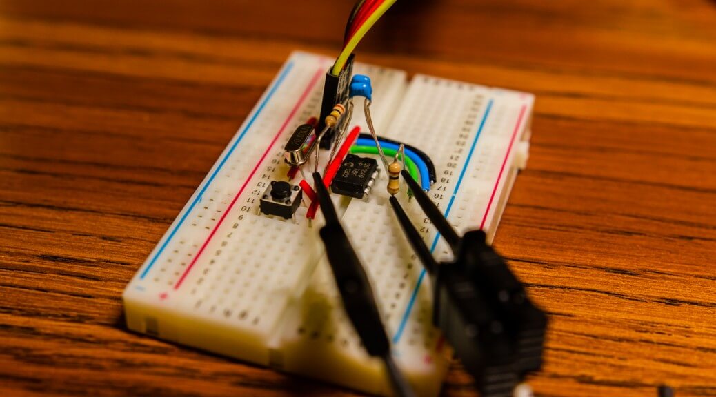
Here’s a fairly simple yet somewhat interesting project that I’ve been working on for the last few days. The idea is to make a simple, configurable ultrasound PWM generator that could be used to drive an electrostatic transducer at low ultrasound frequencies (20 kHz – 200 kHz). To keep parts to a minimum, I used nothing but a PIC12F1840 with a 20 MHz crystal oscillator and a single button for the trigger.
Background
As a bit of a background, the plan was to make a ultrasonic transmitter that could extend upon the functionality of the commonly used SMT6500 ranging modules. The input to the driver is fairly simple: on a rising edge from the INIT input, the module sends out 16 pulses at 49.4 kHz to the electrostatic transducers. While this works great for ranging with single modules, it becomes problematic when you try to use several modules simultaneously as it becomes impossible to discern between the individual transmitters. A possible solution is to allow each transmitter to send its own unique pulse pattern, allowing for the different transmitters to be discerned with a bit of signal processing on the receiver side.
The Details
The microcontroller of choice, a PIC12F1840, was chosen for two reason. The first is because I wanted a microcontroller with a small footprint and this one fits that requirement with only eight pins. Two of the pins are for power and ground, another two are allocated to the UART (for on-the-fly configuration), two more are used for the external crystal oscillator, one is used for the input, and one is used for the pulse output. The second reason was because I already have a decent bit of experience working with this particular microcontroller as I used it for my NeoPixel clock project.
A 20 MHz crystal oscillator is used to drive the microcontroller. I decided to use an external crystal to allow for higher timing accuracy as the internal oscillator can vary by as much as 1%. Using an external crystal also allowed me to run the PIC at a frequency unachievable from using only the internal oscillator block. This is important as it allowed me to drive the output PWM from 20 kHz to 200 kHz without changing the timer configuration. With the PIC being driven at 20 MHz Fosc, the instruction clock is derived to be Fosc/4 or 5 MHz. The timer that drives the internal PWM peripheral is eight bits in size, resulting in a minimum PWM frequency of 5 MHz / 256 = 19.5 kHz with a 1:1 prescaler on the timer. Lower frequencies can be achieved by using a higher prescaler value at a loss of frequency granularity.
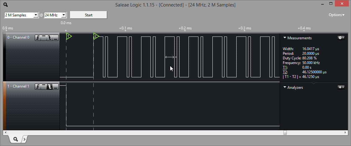
16 pulses (0xAAAA) at 50 kHz with 80% duty cycle for high bits and 20% duty cycle for low bits.
The output pulses are generated using the internal CCP (capture/compare/pwm) peripheral. The PWM portion of the peripheral is fairly simple to operate. Timer 2 (TMR2) is used as the base counter for the PWM signal and runs off the instruction clock (Fosc/4). The period (PR2) register determines the PWM period and the duty cycle is stored in CCPR1L:DC1B registers/bits. Note that the duty cycle register is 10 bits wide while the timer/period registers are 8 bits each. This is due to the fact that within the peripheral, TMR2 is concatenated with the two bit internal system clock (Fosc) or the prescaler bits to create a ten bit time base. When the value in TMR2 matches the period specified in PR2, four events occur simultaneously:
- TMR2 is cleared
- CCP1 output pin is set high (if duty cycle != 0%)
- Duty cycle value is latched in from CCPR1L:DC1B to CCPR1H
- Timer 2 interrupt flag (TMR2IF) is set
When the value in TMR2 matches that in CCPR1H, the CCP1 output pin is brought low. Knowing when the duty cycle values are latched in and when the interrupt flags are set is vital in understanding how to adjust the pulse width on the fly. An excerpt of the pattern transmission function is as follows:
|
1 2 3 4 5 6 7 8 9 10 11 12 13 14 15 16 17 18 19 20 21 22 23 24 25 26 27 28 29 30 31 32 33 34 35 36 37 38 39 40 41 42 43 44 45 46 47 48 49 50 51 52 53 54 55 56 |
void PWM_Transmit_Pattern() { // Set duty cycle to 0% CCP1CONbits.DC1B = 0b00; CCPR1L = 0x00; // Start timer and wait for it to rollover to latch duty cycle value T2CONbits.TMR2ON = 1; while (!PIR1bits.TMR2IF); PIR1bits.TMR2IF = 0; CCP1_TRIS = 0; // Bit 15 if (savedPattern & 0x8000) { CCP1CONbits.DC1B = computedDutyCycleHigh_LowerBits; CCPR1L = computedDutyCycleHigh_UpperByte; } else { CCP1CONbits.DC1B = computedDutyCycleLow_LowerBits; CCPR1L = computedDutyCycleLow_UpperByte; } while (!PIR1bits.TMR2IF); PIR1bits.TMR2IF = 0; // Bit 14 if (savedPattern & 0x4000) { CCP1CONbits.DC1B = computedDutyCycleHigh_LowerBits; CCPR1L = computedDutyCycleHigh_UpperByte; } else { CCP1CONbits.DC1B = computedDutyCycleLow_LowerBits; CCPR1L = computedDutyCycleLow_UpperByte; } while (!PIR1bits.TMR2IF); PIR1bits.TMR2IF = 0; ... // Bit 0 if (savedPattern & 0x0001) { CCP1CONbits.DC1B = computedDutyCycleHigh_LowerBits; CCPR1L = computedDutyCycleHigh_UpperByte; } else { CCP1CONbits.DC1B = computedDutyCycleLow_LowerBits; CCPR1L = computedDutyCycleLow_UpperByte; } while (!PIR1bits.TMR2IF); PIR1bits.TMR2IF = 0; // Set next duty cycle to 0% (idle line low) CCP1CONbits.DC1B = 0b00; CCPR1L = 0x00; // Wait for timer to rollover, then turn off timer while (!PIR1bits.TMR2IF); PIR1bits.TMR2IF = 0; T2CONbits.TMR2ON = 0; TMR2 = 0x0; } |
The disassembly for the transmission of each bit is shown below. According to the instruction set table, it takes 22 instructions cycles to execute the code for determining and setting the duty cycle value for each bit. Thus a minimum of 23 instruction cycles is needed before TMR2 is allowed to match PR2, leading to a maximum PWM frequency of 217.4 kHz at a Fosc of 20 MHz.
|
1 2 3 4 5 6 7 8 9 10 11 12 13 14 15 16 17 18 19 20 21 22 23 24 25 26 27 28 29 30 31 32 33 34 35 36 37 38 39 40 41 42 |
! // Bit 15 ! if (pattern & 0x8000) { 0x26: BTFSS 0x72, 0x7 0x27: GOTO 0x34 ! CCP1CONbits.DC1B = computedDutyCycleHigh_LowerBits; 0x28: MOVLB 0x0 0x29: MOVF computedDutyCycleHigh_LowerBits, W 0x2A: MOVWF 0x73 0x2B: SWAPF 0x73, F 0x2C: MOVLB 0x5 0x2D: MOVF CCP1CON, W 0x2E: XORWF 0x2F3, W 0x2F: ANDLW 0xCF 0x30: XORWF 0x2F3, W 0x31: MOVWF CCP1CON ! CCPR1L = computedDutyCycleHigh_UpperByte; 0x32: MOVF computedDutyCycleHigh_UpperByte, W 0x33: GOTO 0x41 ! } else { ! CCP1CONbits.DC1B = computedDutyCycleLow_LowerBits; 0x34: MOVLB 0x0 0x35: MOVF computedDutyCycleLow_LowerBits, W 0x36: MOVWF 0x73 0x37: SWAPF 0x73, F 0x38: MOVLB 0x5 0x39: MOVF CCP1CON, W 0x3A: XORWF 0x2F3, W 0x3B: ANDLW 0xCF 0x3C: XORWF 0x2F3, W 0x3D: MOVWF CCP1CON ! CCPR1L = computedDutyCycleLow_UpperByte; 0x3E: MOVLB 0x0 0x3F: MOVF computedDutyCycleLow_UpperByte, W 0x40: MOVLB 0x5 0x41: MOVWF CCPR1 ! } ! while (!PIR1bits.TMR2IF); 0x42: MOVLB 0x0 0x43: BTFSS PIR1, 0x1 0x44: GOTO 0x42 ! PIR1bits.TMR2IF = 0; 0x45: BCF PIR1, 0x1 |
If the two LSB of the duty cycle register (DC1B) is ignored, a minimum number of 14 instructions cycles is required for each bit. This corresponds to a maximum frequency of 333.3 kHz at 20 Mhz.
|
1 2 3 4 5 6 7 8 9 10 11 12 13 14 15 16 17 18 19 20 |
! // Bit 15 ! if (pattern & 0x8000) { 0x26: BTFSS 0x72, 0x7 0x27: GOTO 0x2A ! CCPR1L = computedDutyCycleHigh_UpperByte; 0x28: MOVF computedDutyCycleHigh_UpperByte, W 0x29: GOTO 0x2C ! } else { ! CCPR1L = computedDutyCycleLow_UpperByte; 0x2A: MOVLB 0x0 0x2B: MOVF computedDutyCycleLow_UpperByte, W 0x2C: MOVLB 0x5 0x2D: MOVWF CCPR1 ! } ! while (!PIR1bits.TMR2IF); 0x2E: MOVLB 0x0 0x2F: BTFSS PIR1, 0x1 0x30: GOTO 0x2E ! PIR1bits.TMR2IF = 0; 0x31: BCF PIR1, 0x1 |
Due to use limited resolution of TMR2, the gap between achievable frequencies increases inversely with PR2. Thus the accuracy of the PWM frequency is higher at slower speeds.
- 23 instruction cycles @ 5 MHz = 217.4 kHz
- 24 instruction cycles @ 5 MHz = 208.3 kHz
- 25 instruction cycles @ 5 MHz = 200.0 kHz
- 26 instruction cycles @ 5 MHz = 192.3 kHz
- 27 instruction cycles @ 5 MHz = 185.1 kHz
- 247 instruction cycles @ 5 MHz = 20.24 kHz
- 248 instruction cycles @ 5 MHz = 20.16 kHz
- 249 instruction cycles @ 5 MHz = 20.08 kHz
- 250 instruction cycles @ 5 MHz = 20.00 kHz
Serial Configuration
In order to allow users to change settings on-the-fly, I’ve implemented a simple serial protocol that allows adjustment of the PWM frequency, duty cycle values, as well as the bit pattern. Configuration simply involves sending a series of bytes to the device, with the first byte being the op-code. The baud rate for communication is fixed at 19.2k with one stop bit. All non-opcode values will be ignored. Board responds with “Ok!\n” when commands are successfully processed. Valid op-codes are as follows:
- 0x01 = Sets frequency
- Bytes 1-4 = 32 bit unsigned value between 20k and 200k
- 0x02 = Sets duty cycle
- Byte 1 = 8 bit unsigned value (0-100), duty cycle of ‘high’ bit
- Byte 2 = 8 bit unsigned value (0-100), duty cycle of ‘low’ bit
- 0x03 = Sets transmit pattern
- Bytes 1-2 = 16 bit pattern (transmits MSB first)
Future Work
I’m fairly satisfied with the code base as it is, but I may add more features and/or speed optimizations later on. My next step is to build a custom PCB board that combines this microcontroller with the driving circuitry for the electrostatic transducers. I’ll be posting updates here as usual.