This is NOT a guide for those who are new at 3D printing!
My Simplify3D profile can be found here while calibration STLs can be downloaded here
THIS GUIDE IS NOW OUTDATED WITH THE RELEASE OF SIMPLIFY3D v3.0. Please reference Simplify3D’s troubleshooting guide instead.
Getting a perfect 3D print is notoriously difficult, even with a fairly expensive top-of-the-line consumer printer such as the Ultimaker 2. While there are some very good guides out there (see IRobertI’s guide in particular), many of these guides don’t go beyond the basics for calibrating a 3D printer. To address this, I’ve decided to write up a fairly comprehensive troubleshooting and optimization guide tailored for the Ultimaker 2 with Simplify3D (v2.2.2) as the slicing engine. Most of the information in this guide however can also be applied to other 3D printers. All of the following notes and tips are derived solely from my experiences. Detailed macro photographs are provided to back my observations and also serve as a comprehensive visual aid.
Problem within prints are often caused by a combination of issues rather than having a single contributing source of error. Rather than re-addressing the topics covered in introductory guides, I’ll assume that readers of this guide have read and followed the tips and tricks in IRobertI’s guide and have a decently working printer. Specifically I’ll assume that you have meet the following prerequisites:
- Your printer works and can print with satisfactory results
- There are no major quality issues with your prints in terms of over/underextrusion, top-fill, etc
- Both the printer and print bed are properly leveled
- Quality filament is used
In order to provide high quality examples, I am using my custom fan mount along with my custom filament extruder. All prints were made using white 3mm ABS filament from lulzbot.com on an Ultimaker 2.
Heated Bed and Print Adhesion
A properly leveled bed is mandatory for good quality prints. In addition to the leveled bed, the method of increasing surface stickiness is important as well. The Ultimaker 2 comes with a fairly flat glass bed that is attached to the heated plate through metal clips on the corners. This allows the glass bed to be easily removed for cleaning and also allows for easy part removal. To help with bed adhesion, I’ve found that Elmer’s Disappearing Purple School Glue Sticks works far better than blue tape or hairspray. It’s also water soluble so cleaning simply involves rinsing the bed under hot water for a few minutes.
Prior to printing, put two layers of glue on the glass in an area slightly larger than the part being printed. The temperature should then be increased to 90° C (for ABS) immediately while the glue is wet. If the glue is allowed to dry, the extra adhesion provided by the glue is heavily reduced. Once the print is finished, the hot-bed should be turned off to allow the glass to cool. Once the glass has cooled to <60° C, the print should begin to pop off by itself as ABS naturally shrinks as it cools. Once the print has popped off (~40° C), the glass bed can be rinsed under hot water to remove the layer of glue before another print is started. Total downtime between prints is less than 5 minutes if a fan is used to actively cool the glass bed.
The height of the first layer is also important in determining how well the print adheres to the glass bed. From firsthand experience, the first layer height should be calibrated to roughly 80% of the layer height. This does result in a slightly wider base for the first layer, but it’s an issue easy fixable with a bit of post print cleaning. Print speeds should also be slower for the first layer at around 60% of normal printing speed with the cooling fan turned off.

Filament Extruder
Having a reliable filament extruder is an essential requirement for achieving the best prints. For most use cases, IRobertI’s filament extruder has higher consistency than the stock filament extruder. For prints with unusually high retractions however, I have my own custom filament extruder that has yet to fail a single print.
The important thing to note with the filament extruder is that there are two stages of failure. The first and most obvious failure is when the hobbed gear fully strips the filament, causing the filament to stop advancing until the user manually intervenes. This is pretty much guaranteed to cause havok on the resulting print. The second failure is when the hobbed gear partially strips the filament. This occurs when the filament slips by a minor amount, often less than a few millimeters. When this occurs, the filament is still extruded but there is a noticeable decrease in print quality, often resulting in underextrusions.


Extruder Settings
Trying to figure out the right combination of settings for the extruder is incredibly difficult as each setting will often change the impact of other settings. For instance, using a lower value for the extrusion multiplier (to get smoother outer walls) means that you’ll need to reduce the extrusion width (to prevent gaps in the top/bottom layers). Using too low of a value for extrusion multiplier and width however results in gaps between the solid infill and the outline shells as well as affecting the strength and stability of the non-solid infill.
The three main areas to pay attention to are as follows. Settings that impact the quality of each area is given along with a brief description of the impact of individual settings.
- Outer wall quality:
- Extrusion Multiplier : underextrusion if set too low, uneven layers if set too high
- Wipe Distance : z-seam if turned off, extra ridges if too high
- Outline Shells : more shells = higher wall strength, smoother outer wall
- Printing Speed : slower = higher consistency
- Outline Underspeed : too slow = inconsistent extrusions due to varying print speeds
- Top/bottom layer quality:
- Extrusion Multiplier : underextrusion if set too low, uneven surface if set too high
- Extrusion Width : determines spacing between parallel lines, gaps if set too low
- Retractions : off = lines across surface, results in uneven surface
- Outline Overlap : Removes gaps between solid infill and outline shells
- Top/Bottom Layers : more layers helps to fill in gaps when using sparse infills
- Solid Infill Underspeed : slower speeds result in wider lines but higher print speed variation
- Infill Extrusion Width does NOT make a difference here!
- Infill strength and quality:
- Extrusion Multiplier : ;underextrusion if set too low
- Extrusion Width : lower values results in denser infills
- Interior Fill Percentage : density of infill, multiplier of extrusion width
- Outline Overlap : lower values = gaps between infill and outline shells
- Infill Extrusion Width : higher percentages increase the infill extrusion amount
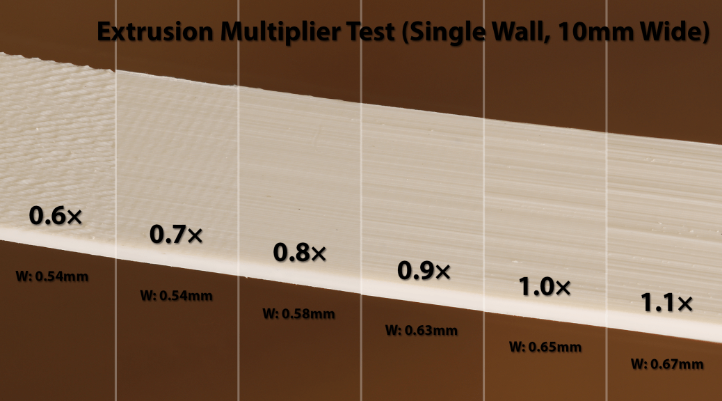
Extrusion Multiplier:


Extrusion Width (Solid Infill):


Extrusion Width (Sparse Infill):


Outline Overlap:


Extruder Wipe Settings:


A Note on Part Dimensions
The dimensional accuracy for printed parts is almost entirely determined by the extrusion width. The outermost line of the outline parameter is moved inwards by half the extrusion width value on either side of the print. In the ideal scenario, the extrusion width value should be set to the same width as measured in a single-wall print. As we can see in the sections above however, the extrusion width needs to be lowered to get sufficiently high quality solid and sparse infills. When a lower value is used for the extrusion width is used, parts will turn out slightly wider. This extra width then needs to be accounted for when designing the part itself.
Printed parts can have high dimensional accurately however if Simplify3D implemented three additional settings. The first is to allow the user to specify the extrusion multiplier for the solid infill layers. The second is to allow the user to specify the extrusion multiplier for the sparse infill layers. A side effect of adding this option is that it would allow for extremely strong sparse infills at a relatively low infill percentage. The third option should allow the user to change the spacing between the outer parameter lines as using the ideal extrusion width value can results in small gaps between the parameter lines.
Unfortunately, the team behind Simplify3D decided to implement dimensional accuracy another way. Rather than providing the options to properly tune the extruder, they decided to add a Horizontal size compensation parameter to literally shrink the model in the X-Y plane prior to printing. This, as you may guess, causes some problems with certain designs.


A Few Other Notes
- Retraction distance and speed should be adjusted based off the capabilities of your extruder
- Coasting and extra restart settings causes inconsistencies with high retraction prints
- Large changes in print speeds has a large effect on print quality
- Using random start points for all parameters works best, results in seamless prints
- Sparse Infill should be turned off, otherwise results in certain layers being printed faster than others