Design files for this project can be found here.
3/16/2015 – Revision C update
6/25/2015 – Download link for my custom software added
Here is a design for a precision paste dispenser that I’ve been working on for the last few months. The goal of this project was to build a solder paste dispenser with a focus on consistent performance, 3D printable design, and minimal use of extraneous parts. While other designs exist (see here, here, here, here, or here), none of the existing designs are capable of low-volume paste dispensing at a consistency required for surface mount parts. These existing implementations are inherently limited by their design: they all use basic pneumatic or belt driven systems that simply don’t offer enough control. Commercial solutions certainly exist (see the Nordson’s EFD series, Fisnar’s PDV-1000 and RV5000DPM, IntelliSpense’s Auger Valve system, Techcon System’s TS7000, and Nordson ASYMTEK Spectrum II) but they usually run well into thousands of dollars ($5k+) for a basic system.


Background
I decided to pick up this project for two reasons. The first and main reason is for the AMP Lab: I wanted to lower the bar for projects involving surface mount parts. While hand soldering SMD parts on a one-off basis isn’t particularly difficult, it certainly is a rather tedious task that requires a significant (days/weeks) amount of practice in order to get good/consistent results. As many of the lab’s members have little to no experience with even through-hole soldering, SMD parts are rarely (if ever) used in projects. Unfortunately more and more chips are moving to SMD-only footprints these days so if you wanted to put together a truly interesting project (such as my LED cube), you would have to spend a significant amount of time outside of the project itself learning and practicing the specifics of SMD soldering. If the paste application process was automated however, the barrier of entry would be lowered enough to easily allow someone with basic soldering experience to put together boards involving SMD parts. A fully automated solution including a reflow oven would dramatically simplify the process.
The second reason why I wanted to work on this project is that at the time, there were no 3D printable precision paste dispenser designs available in public repositories. Existing designs exists (and are linked above) but none of the designs were even close to the precision required for paste dispensing. Most designs used a syringe along with some sort of mechanism to actuate the plunger. Direct drive via a thread rod or belt driven systems seem to be pretty popular. In order to achieve high precision however, one should look at how commercial systems operate. It would be nice to design a system that could achieve close to the same level of performance as commercial systems, but at a vastly lower cost. Ideally, the system should cost under $200 (not counting the 3D printer itself) and should be mountable as a replaceable head onto an existing 3D printer’s gantry system.
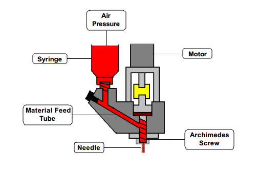 Rather than extruding directly from a pressurized syringe, a mechanical drive system would allow for much finer control over the extrusion amount. I won’t be going into the finer details on how commercial systems operate, but the picture on the right should be largely self explanatory. The idea is that pressurized solder paste is fed into an Archimedes screw. To extrude paste, the screw would rotate and compress paste into the needle. This blog post and PDF contains some excellent information on such designs.
The paste dispenser should achieve the following goals:
- It has to be able to consistently dispense paste for 402 sized SMD pads
- It has to be trivial in both tuning and usage
- It has to be mostly 3D printed with a minimum amount of extraneous parts
- It has to be mountable onto the gantry system for an existing 3D printer
Revision A
For the first revision, I wanted to test the viability of a 3D printed design. For the Archimedes screw, I used a small M5 thread-forming screw that had a fairly large pitch. The screw is epoxied onto a screw mount, which is then attached to a motor mount piece that screws onto an 5mm aluminum mounting hub. A 9mm ID x 2mm W o-ring was used to seal the area between the two rotating surfaces (the base piece and the screw mount). A syringe adapter was used to connect the end of the paste syringe to a small air compressor.
This design actually worked pretty well as it was capable of a fairly consistent extrusion rate when the paste syringe was pressurized at around ~5 psi. There were a few issues however. The first major issue was that the output regulator on the air compressor was pretty inconsistent at low pressures. This should be fixed by attaching a small, dedicated low-psi regulator to the output of the air compressor.
The second issue was the o-ring sealing between the base and the screw mount. The screw mount side of the design had to be pressed against the o-ring in order for the seal to properly work, but too much pressure would cause the stepper motor to skip. I ended up printing precision spacers that sit on the motor shaft to provide the necessary clearances, but this is an ongoing topic for improvements.
The third issue was that the design was too difficult to print. Supports were necessary, but only in certain places of the design. Simplify3D was my slicer of choice so it wasn’t too much of an issue as I could specify my own support structures to be printed. For others though, this may prevent the design from being printable. This should be addressed in the next revision.


")


Revision B
For the second revision of the design I made it so that the entire design could be printed without any support structures. Functionality was tested with the paste pressurized at 8 psi. Dispensing was entirely electronically controlled, with each dot consisting of the screw rotating 720° counter-clockwise and then 360° clockwise to retract the paste and prevent it from drooling. Different dot sizes can be achieved by changing how much the screw rotates. As it can be seen from the results, consistency was excellent across the entire test.
Low pressure regulation was achieved using a miniature 0-10 psi regulator with a 15 psi pressure gauge attached. A custom 1/4 in NPT to 1/8 in ID tubing adapter was designed to connect this regulator to the tubing.
As this revision seems to work pretty well, my next focus is to create a custom head mount to replace the 3D printing head on the KITTAZ gantry system.


")


Revision C
A significant number of improvements were incorporated into the third revision of the paste dispenser. The rubber o-ring were replaced with PTFE v-ring seals and the original M5 12mm long screw was replaced with a M4.5 screw that is 14mm in length. Both the base piece as well as the spacer unit were redesigned for the new parts, and the spacer/syringe holder piece now has mounting holes incorporated into the design. The screw mount was also simplified down to a single piece and is now significantly smaller than the one in the previous revision. A mounting plate for the LulzBot TAZ4 3D printer frame was also designed to securely mount the paste dispenser onto the gantry system.
While this revision works pretty well, there are a few aspects of the design that can be further improved. The most pressing issue is that lower-viscosity paste (new tubes or ones with high flux content) will still leak out from the v-ring seal, even when there is enough pressure between the seals to cause the stepper motor to skip. The reason for this is mostly likely because the shaft from the stepper motor isn’t perfectly centered with the rest of the unit, thereby causing a minor gap between the v-ring seal pieces when the screw mount is rotating. Using a flex shaft coupler might fix this problem. Mounting the screw head on the flex shaft coupler however may be difficult. For the current design though, using a minimal amount of pressure (0.5-3 PSI) works well enough to keep the paste from escaping. If and/or when the paste leaks out, the slots on the side of the print head act as an escape port for the leaked paste, thus allowing for easy cleanup.
Another improvement to the design would be to increase the screw’s length from 14mm to 20mm or longer. The extra length would allow for more precise control and higher paste pressures. Sourcing such a screw however has proved to be difficult as the size needs to be M4 or larger while the threads have to be wide enough to hold the solder paste.


Bill of Materials
- 13x M3 10mm Screws
- 4x M3 16mm Screws
- 12x M3 Nuts
- 1x M/F V-Ring Seal (3/8″ ID, 3/4″ OD)
- 1x M4.5 14mm Threading Screw
- 1x Luer-Lock Nozzle
Software
The code for this project can be downloaded here
The software interface for driving the paste dispenser is entirely custom written in Qt. In addition to having the functionality of a basic serial terminal, I’ve also added in comprehensive macro functionality complete with user customizable hotkeys. For the paste controller interface, I’ve included all possible settings that I could think of to give the user full control of the paste extrusion process. The only remaining feature to implement is the ability to read and print a solder paste mask from the corresponding Gerber file.
An important thing to note however is that the Marlin firmware itself needs a few changes before it can be used for paste dispensing. In addition to turning off the extruder/hotbed heater, support for the SD card as well as the LCD needs to be disabled to improve the software response time. Specifically:
- Set TEMP_SENSOR_X in Configuration.h to 0 to disable temperature sensors
- Comment out all SDSUPPORT blocks to disable SD card polling
- Comment out lcd_update() in Marlin_main.cpp to disable LCD interrupts
- Add #ifdefs or comment out all references to HEATER_0_MAXTEMP in ultralcd.cpp


