The latest code base for the controllers can be found here
12/28/2013 – Added Revision A Section
1/20/2014 – Added Revision A PCBs
1/26/2014 – Added Revision B Design
2/28/2014 – Populated Revision B Boards
As I had to take the LED cube home for a few days to fix a few things, I figured that I might as well extend its functionality. As such, I decided to add gaming functionality to the cube! To do so, I first had to design a controller to provide some way to interact with the cube. Originally I had hoped that someone from the AMP lab would take on this project, but no one seemed interested to do so (probably because it was finals week). Perhaps they would be more interested in programming games for the cube?
The controllers themselves should be pretty simple: a few buttons for inputs and some LEDs for things such as score indications. As such, it should be a relatively quick project. Perhaps I could put some sensors on the board as well, allowing for some gesture based control.


")
Prototype
The first prototype of the controllers that I came up with were pretty simple: six input buttons (one for each direction) and 4 indicator LEDs. The controllers are polled and controlled through a basic I2C protocol, with each controller having a hard coded address. The connecting cables were custom made using this amazing 4-wire silicon cable and standard female headers. I also had to build an I2C breakout for the Cerebot board in order to be able to attach more than two controllers. Nothing beats using perma-protoboards for finalizing a breadboard design.
As for the games, I spent a few hours implementing both a game of Snake and Tron on the cube. By using the software reset capability of the PIC32 microcontroller, I’ve set it so that the cube automatically resets to an idle state every 15 minutes or so where it loops through a preset list of animations. If a button is pressed on either of the controllers, the cube goes into Snake mode. If both buttons are pressed, the cube goes into Tron mode. Both games are surprisingly hard to play in 3D.
Over this winter break, I’m planning on designing and putting together an actual PCB with ideally eight buttons, some feedback LEDs, and maybe an OLED display or two.


Controller Rev. A
For the first PCB revision of the controller, I decided to expand the number of features. I increased the number of LEDs from 4 to 16, and the number of buttons from 6 to 10 (of which two are capacitive). To handle the increase in I/O, I decided to use the TLC59116 chip for driving the LEDs and the MCP23009 chip for reading in the button values. The TLC59116 chip is a 16 output I2C LED driver with 8 bits of resolution. Similarly, the MCP23009 chip provides the capability to interface with 8 I/Os over I2C. In addition to these two chips, I also added the LSM303DLHC (accelerometer/magnetometer) and L3GD20 (gyroscope) chips to the board.
For the microcontroller, I went with the PIC16F1829 as it has two separate I2C interfaces. One of the I2C interface (I2C1) will implement the slave side of I2C for communication to the Cerebot board. The other I2C interface (I2C2) will implement the master side of I2C to communicate to the other chips on the board. Four of the pins are used as I2C address jumpers, allowing up to 16 controllers to exist on the same I2C bus. The rest of the pins are used as interrupt pins from the various chips on the board. I’ve also added a few minor features: two capacitive buttons, I2C pullup resistors, a main power switch, and a UART debug port for the microcontroller. Overall, this board should have more than enough functionality for the variety of games that I would like to implement.

")
")
")
")
")
")
")

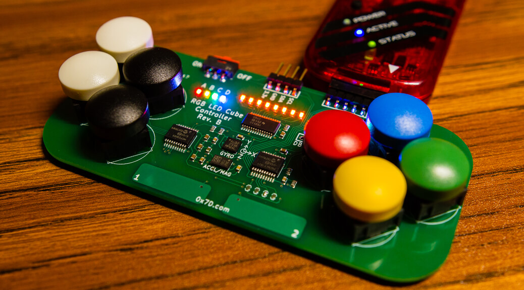
Controller Rev. B
Before making some of the changes mentioned above to the controller PCB, I first tested the functionality of the first revision board by writing some preliminary code to ensure that everything worked as expected. As it did, I then went ahead with the PCB redesign. The following changes were made for revision B: I first fixed the button footprints and spaced out the buttons properly to ensure that none of the buttons overlapped. Because of the increase in button footprint spacing and size, quite a bit of extra board real-estate had to be allocated to the buttons. As such, I had to change the footprint of the PIC18 chip as well as the MCP23009 chip to SSOP-20 from SOIC-18. I also flipped the silkscreen 180 degrees as it felt more natural to have the D-pad on the right side. I’ll be sending the design to the fab house ASAP, so I should have the new boards in in just over a week.

")
")
")


