Boost Topology
In the boost topology, the steady-state voltage across the inductor is zero during the idle period when the circuit is inactive. When the switch is turned on, the voltage across the inductor increases to Vin. When the switch is turned off, the voltage drops to Vin-Vout at the switch/output node. As both input and output voltages are constants, the current’s on-time slope is:
(1) ![]()
Similarly, the current’s off-time slope is:
(2) ![]()
The peak current through the inductor is the current slope times the on-time:
(3) ![]()
When the boost circuit is operating in CCM the volt seconds across the inductor during the on-period must be equal to the volt seconds across the inductor during the off-period. The volt second during this period is the current slope multiplied by the corresponding time the switch is on or off:
(4) ![]()
This equation can be solved for the minimum duty cycle required to keep the circuit operating in CCM:

(5) ![]()
In DCM, the discharge time can be found by dividing the peak current (volt second during the on-time) with the current slope during the off-time:
(6) ![]()
The discharge duty cycle is then the discharge time over the switching time:
(7) ![]()
In steady state operation, the average output current is equal to the average diode current which is equal to the peak current averaged over the switching period:

(8) ![]()
This can then be solved to find Ddcm given the input and output voltages, the switching frequency, and inductance:
(9) ![]()
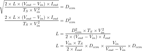
To find the inductance value required to keep the duty cycle above the minimum required for CCM, set the DCM duty cycle equal to the CCM duty cycle and solve for the inductance:

(10) ![]()
For more accurate results, include the forward voltage drop of the rectifier diode in the output voltage.
Flyback Topology
There are number of major differences introduced by the transformer choke used in the flyback typology. The first relates to the voltage relationship across the windings when current is flowing in one of the winding. An active current across the primary winding will induce a voltage on the secondary winding proportional to the winding ratio:
(11) ![]()
Efficiency is high, so power is conserved between the windings. Because power in conserved, the current on the secondary winding is inversely proportional to the winding ratio:
(12) ![]()
The inductance of the primary winding is usually provided in the datasheet for the transformer. The inductance of the secondary winding is equal to the primary inductance times the square of the winding ratio:
(13) ![]()
Using the above knowledge, the same steps can be taken to derive the formulas for flyback components. Identical to an inductor, the current’s on-time slope is:
(14) ![]()
The current’s off-time slope is different however due to the difference in inductance between the windings. Furthermore, the voltage across the secondary winding drops all the way to zero when the circuit is idle:
(15) ![]()
The peak currents through the primary winding is the same as in an inductor. The peak current through the secondary winding is inversely proportional to the winding ratio:
(16) ![]()
When operating in CCM, the transformer choke’s volt second during the on-period is equal to the volt seconds during the off-period. In the same way that the induced voltages is proportional to the winding ratio, the volt second of the secondary winding is proportional to the volt second of the primary winding:
(17) ![]()
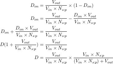
This can be used to solve for the minimum duty cycle required to maintain CCM:

(18) ![]()
In DCM, the discharge time can be found by dividing the peak current (volt second during the on-time) of the secondary winding with the current slope of the secondary winding during the off-time:
(19) ![]()
The discharge duty cycle is then the discharge time over the switching time:
(20) ![]()
In steady state operation, the average output current is equal to the average diode current which is equal to the peak current of the secondary winding averaged over the switching period:

(21) ![]()
This can then be solved to find Ddcm given the input and output voltages, the switching frequency, and inductance:
(22) ![]()
To find the inductance value required to keep the duty cycle above the minimum required for CCM, set the DCM duty cycle equal to the CCM duty cycle and solve for the inductance:

(23) ![]()
For more accurate results, include the forward voltage drop of the rectifier diode in the output voltage.