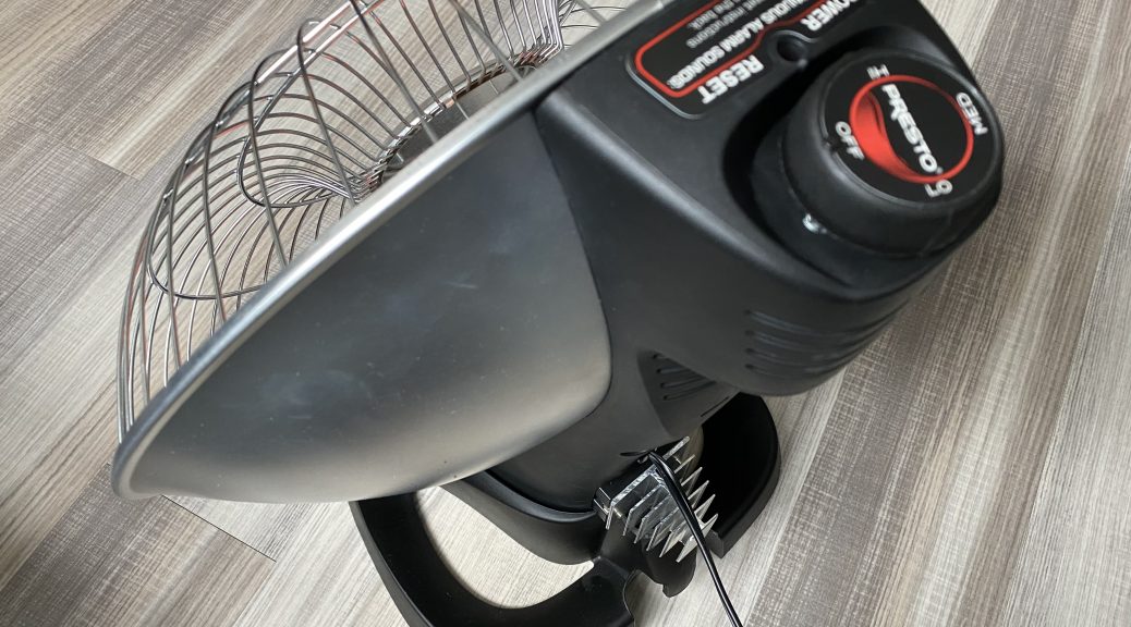
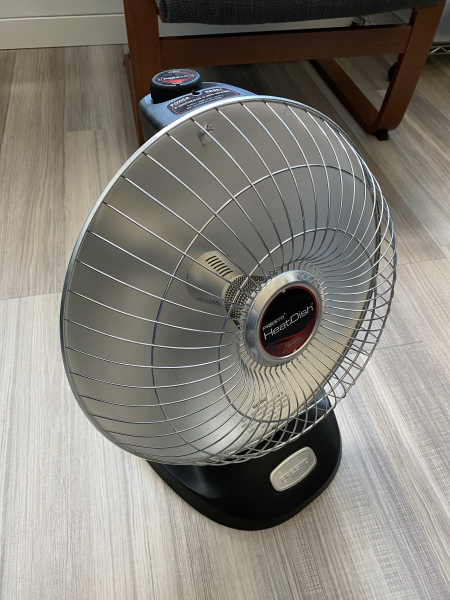
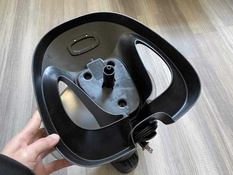
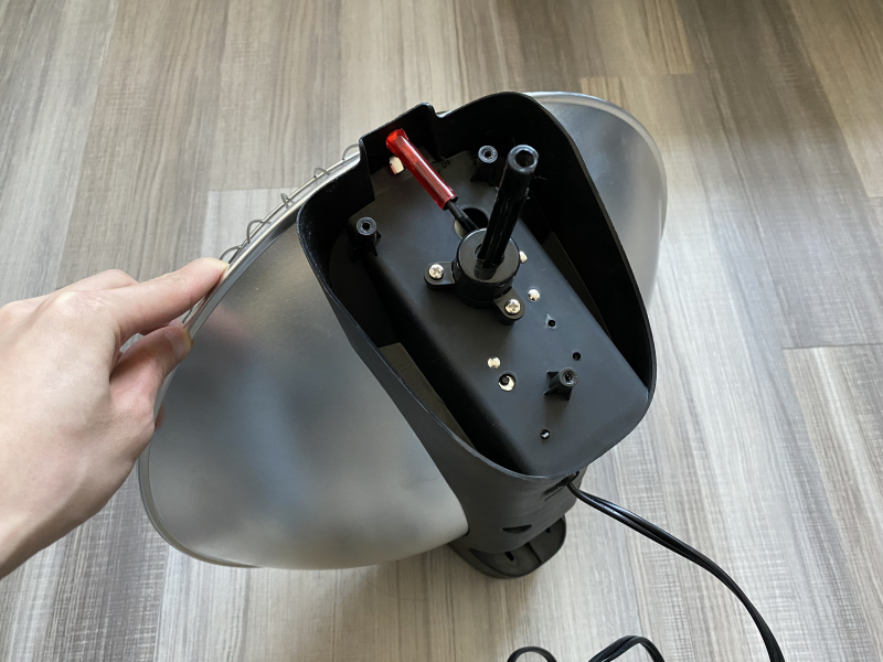
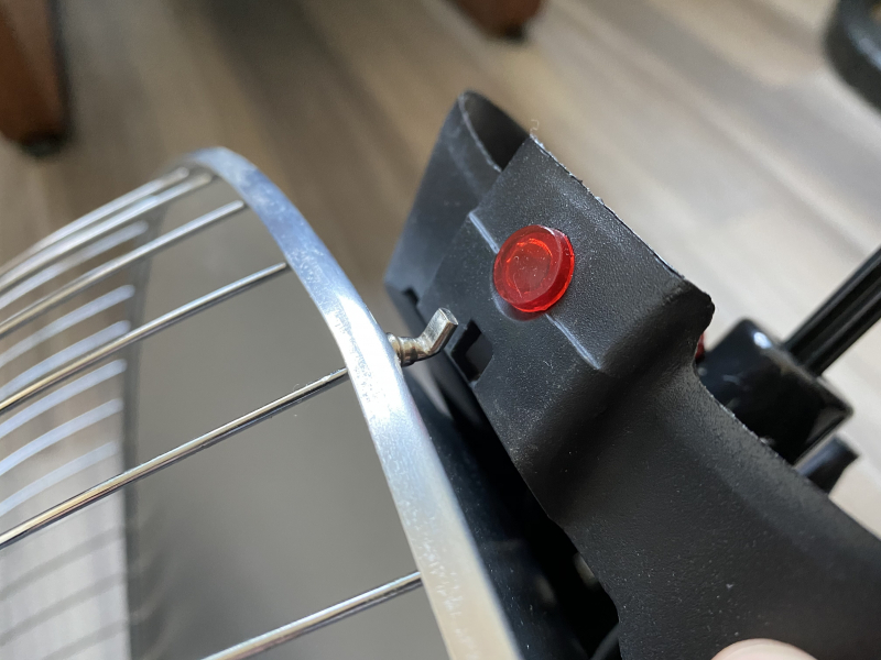
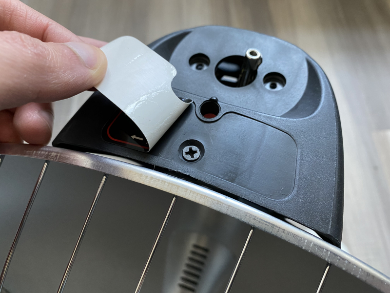
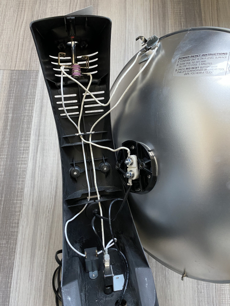
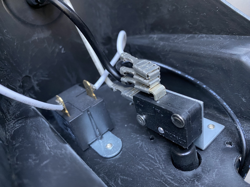
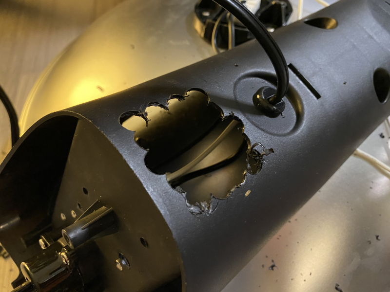
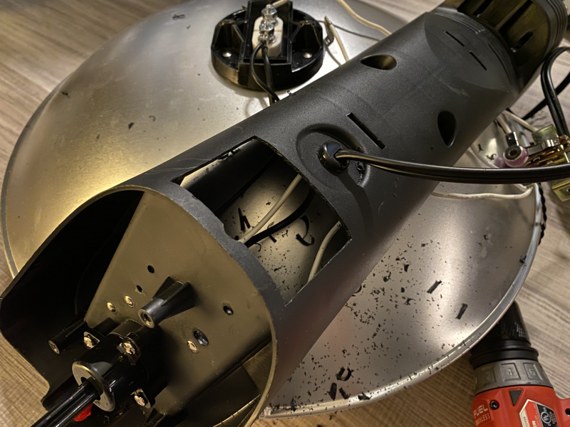
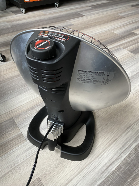
Here’s a small weekend project that I worked on to address a few small annoyances that I had with my Presto HeatDish Parabolic Heater. The goal here was to replace the internal temperature regulator with a solid state relay driven with a variable frequency PWM signal for faster switching frequency, improved control sensitivity, and wider operating range while maintaining existing safeguards such as tip over and overheating protection.
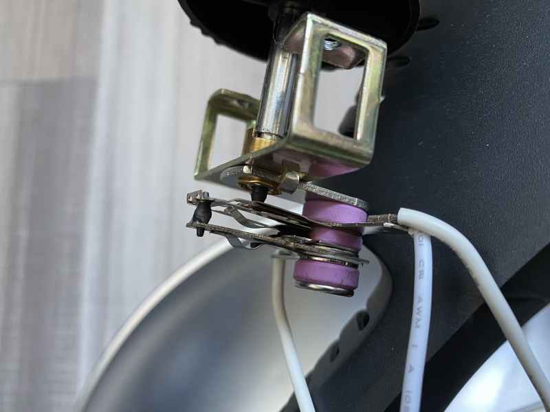
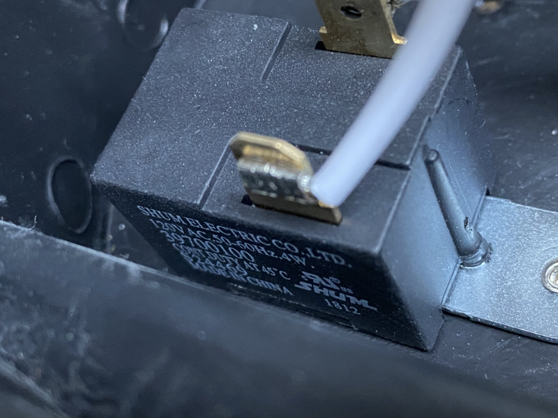
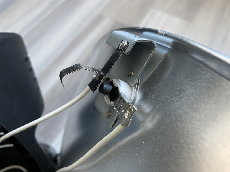
The problem with this heater is that the built-in temperature regulation is quite lacking; at its minimum heat level, the internal regular runs on a cyclic period of ~22s with the heater turned on for ~13s. Furthermore, the regulator runs the heater at 100% duty cycle when the temperature setting dial is set to merely 40%. On top of all that, the internal regulator makes a annoyingly loud click similar to a mechanical relay whenever it switches on or off.
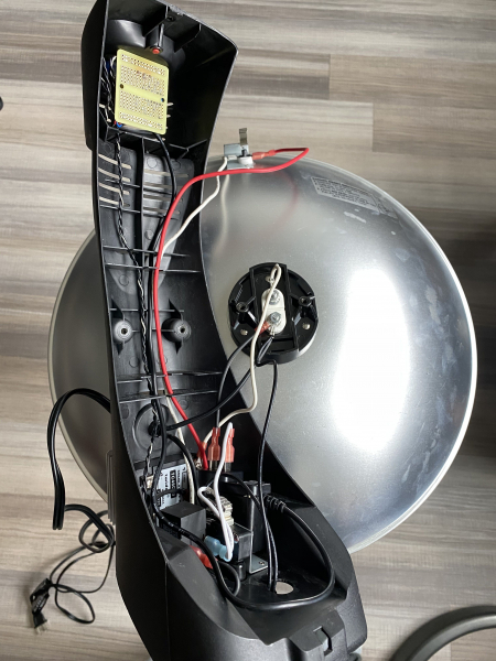
The electrical schematic for the Presto HeatDish is refreshingly simple with only a few analog parts. The temperature dial is connected in series with the heating element and relies on heat expansion of a bi-metallic strip for toggling the switching contacts. The thermal fuse and tip over switch are connected in series, and the two are connected in parallel to the buzzer so that the buzzer will sound if either trips. The temperature switch and heating elements are connected in series to the other elements on the neutral leg of the circuit.
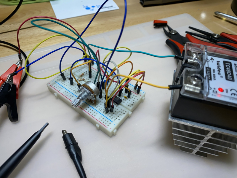
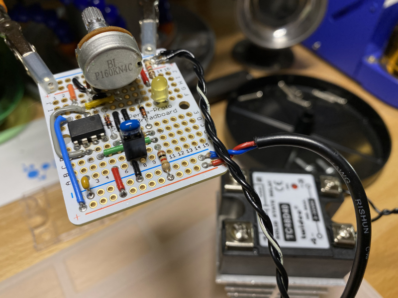
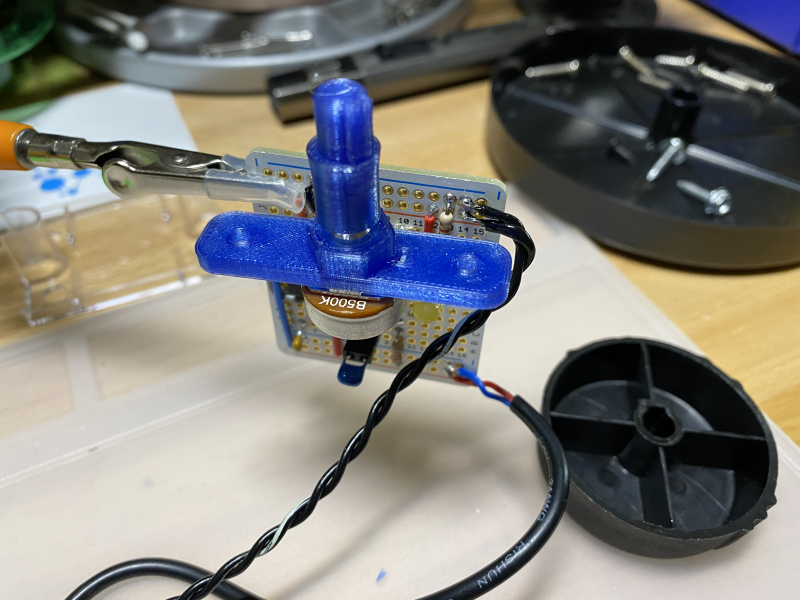
For the modifications, the temperature controller was replaced with an solid state relay (SSR). The SSR is driven by a logic level PWM signal generated from a 555 timer running in astable mode. A potentiometer is used to change the duty cycle of the PWM signal while maintaining a constant switching frequency. This multisim circuit shows what the circuit looks like. The only modifications I made to this circuit was to change the variable resistor range to 420kΩ and the capacitor value to 10μF to get a PWM period of ~3.5s. A small 5V AC adapter was repurposed to power the 555 IC. Note that the capacitor was left unsoldered to allow for easy changes to the PWM frequency.
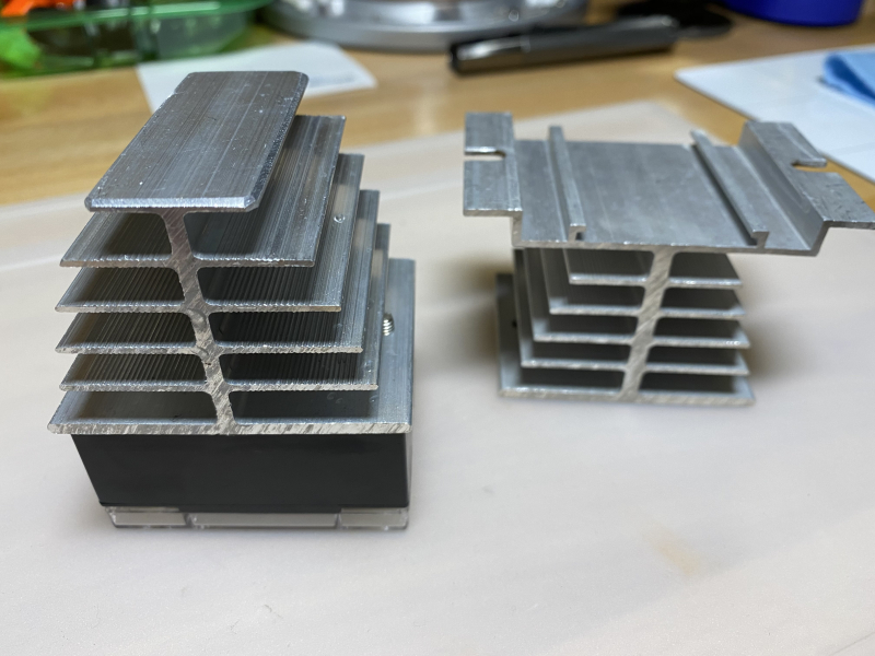
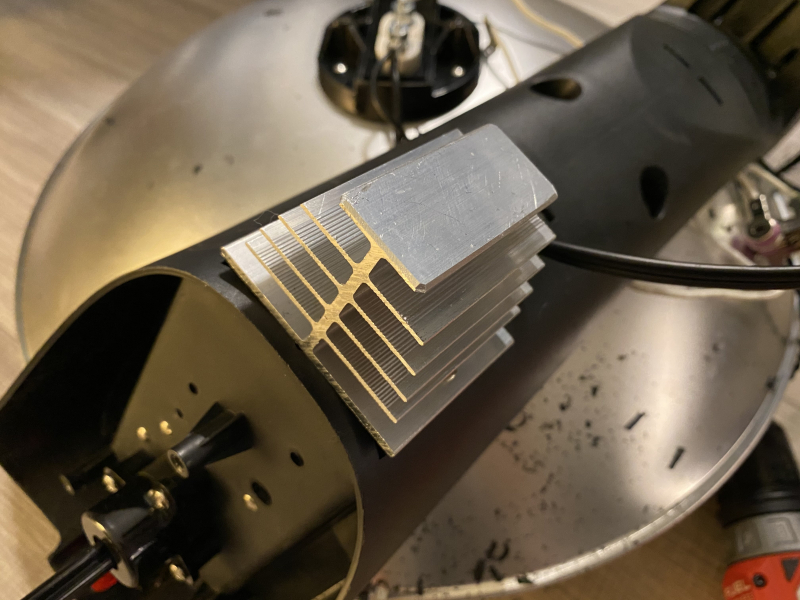
The heater is rated for 1000W, so the maximum continuous current through the SSR should be around 8A. The SSR that I used was rated for 40A, but as it was one of the cheap ones from Amazon I wouldn’t trust it for more than a quarter of it’s rating unless it was actively cooled.
Extended testing was done once the heater was reassembled to ensure that the SSR doesn’t overheat. The heatsink was hot to the touch after leaving the heater on for a few hours at 100% duty cycle in an environment with minimal airflow. IR thermal measurements at the connection point between the SSR and heatsink returned 49°C, or 24°C above ambient which is a acceptable for a passively cooled system. Once it was confirmed that the temperature of the SSR was stable, both the SSR and heatsink assembly was epoxied to the plastic frame for long term durability.
