Design files for this project can be found hereParts have been designed to be 0.3mm larger. This should be taken taken into account when printing.
10/6/2014 – Added video
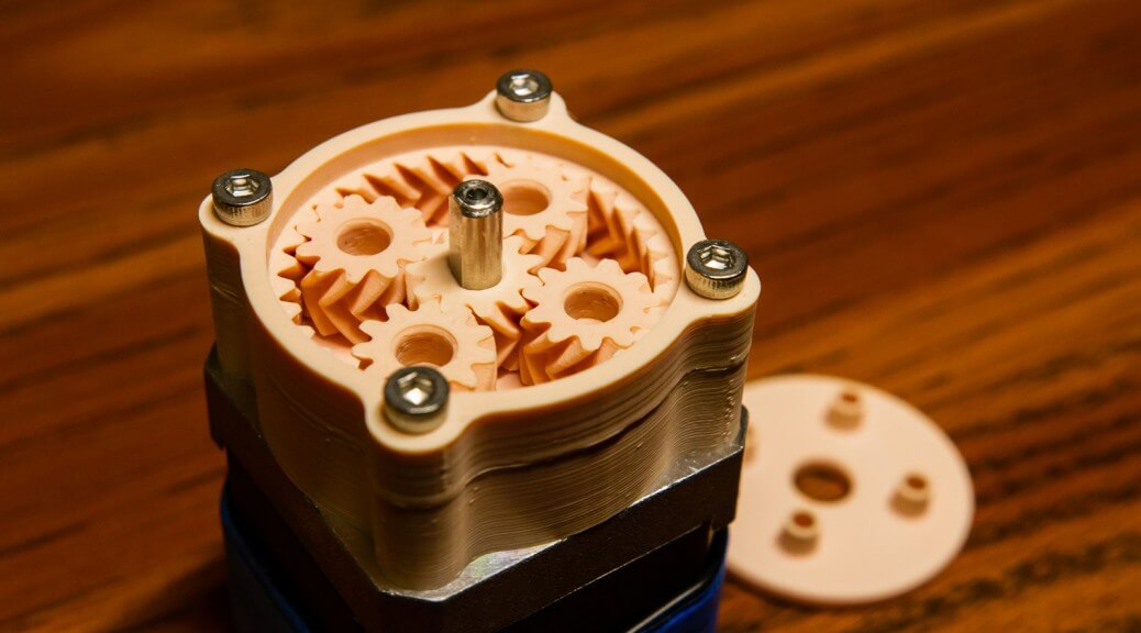
Here is a design for a low-profile (18mm) stackable gearbox that fits onto a standard NEMA 17 stepper motor. The gearing ratio of 4:1 allows for increased torque and positional accuracy from the motor. Herringbone gears are used to provide smooth power transmission from the stepper motor while eliminating the need for thrust bearings. A flat rotating output platform is also provided to allow for easy mounting of attachments.
In order to print helical gears that mesh perfectly with no backlash, a good understanding of the printer used to print the 3D model is required. In my case with the Ultimaker 2, prints are ~0.3mm larger than designed. As such, a 3D printed rod designed with a diameter of 7.7mm will come out to be ~8mm and will fit perfectly (with a bit of friction) into a printed hole with a diameter of 8.3mm. If a looser fit (and thus lower friction) is desired, an additional ~0.05mm to ~0.1mm can be subtracted from the size of one of the components. Knowing the exact size of the resulting prints from the printer is paramount when designing precision parts.


Guide to Designing Gears for 3D Printing in Autodesk Inventor
The following process was mostly obtained through trial and error; your milage may vary.
Autodesk Inventor has a built in spur gear model generator that is also capable of creating helical gears. The design accelerator can be accessed in a saved Assembly file (.iam) under the Design tab through the Spur Gear option. In this component generator, a number of options are available to the user. The most important options include the desired gear ratio, the module size, center distance, pressure angle, helix angle, and number of teeth for each of the gears.
Starting from the top left, I would suggest setting the Design Guide to Center Distance when starting a new set of gears. This allows you to set the Total Unit Correction to 0ul (‘ideal’ gears), allowing for more flexibility when later fine-tuning the spacing in-between gears. To get close to the desired spacing between gears, the number of teeth on the driving gear (Gear 1) can be adjusted. To further fine tune the spacing, the design guide can be set to Total Unit Correction and the Center Distance value adjusted while keeping the Number of Teeth value the same. The Unit Correction Guide should be set to In Gear Ratio for the entire duration of the design process.
If the gears to be designed are external gears, the desired gear ratio can be left alone at 1ul. If internal gears are desired, the ratio should be set to the calculated ratio. The module determines the teeth size of the gears, and can be approximated by the pitch point / π. The Pressure Angle can vary from 14 to 30 degrees, with 20 degrees being a commonly selected choice. The Helix Angle is used when designing helical gears, and can vary from 0 degrees (regular spur gear) to 45 degrees or more. The Facewidth of the gears specify the gear’s thickness. For this gearbox, a gear ratio of 3ul was used for the internal gear, a module size of 0.8mm was used for both gears, and a helix angle of 40 degrees was specified.
For internal gears, the Center Distance should be set to 0.1mm greater than the desired spacing in between gears. For external gears, the Center Distance should be set to 0.1mm less than the desired spacing. For this particular project, a center distance value of 11.5mm was used for the internal gear while the external gears had a center distance of 11.3mm. The actual spacing between the center of the gears was 11.4mm. This difference must be taken into account due to the prints ending up slightly larger than designed. Furthermore, when exporting the designed gears, a Normal Backlash value of 0.1mm should be specified.
Note: printing small gears is a retraction heavy process. A non-slip extruder (ex. my design) is highly recommended.
Step-by-step Process
- Design gears by setting the values described above.
- Ignore any design failure errors that may pop up.
- Export the design by right-clicking the designed gear on the left Model pane and selecting Export Tooth Shape.
- Pinion = Gear1, Gear = Gear2.
- Specify a Normal Backlash value of 0.1mm.
- Using the Coil feature, select the profile of the teeth and select the Z Axis as the axis to rotate around.
- Flip the axis orientation, set the operation to cut, and choose the desired rotation.
- Under the Coil Size tab, set Type to Pitch and Revolution
- Set Pitch to PitchDiameter * PI / tan(HelixAngle)
- ex. 11.30 mm * PI / ( tan(40.00 deg) * 1.000 ul )
- For external gears, the pitch diameter is the Center Distance value
- For internal gears, the pitch diameter should be the diameter of the gear.
- This value is specified as d in the component generator.
- Set Revolution to FaceWidth * tan(HelixAngle) / ( PitchDiameter * PI )
- ex. 4.000 ul * ( tan(40.00 deg) * 1.000 ul ) / ( 11.30 ul * PI )
- Use the Circular Pattern feature to duplicate the cut around the outside of the gear.
- Set the placement count to the number of teeth.
Epicyclic (Planetary) Gear Design
Planetary gears consists of four parts: the sun gear in the center, the planet gears, the carrier that holds the planet gears, and the annular gear that runs on the outside. Either the carrier or the annular gear is typically held stationary, and the resulting gear ratio changes depending on which pieces are allowed to rotate. If the carrier is held, the ratio is -Ns / Na where N denotes the number of teeth on the sun gear or annular gear. If the annular gear is held, the ratio becomes 1 / (1 + Na / Ns). If the sun gear is held, the ratio is (Ns + Na) / Na.
If more planet gears are utilized in the design, the load ability and torque density of the gearing system increases. In order to ensure that the gears fit together, Na = 2 × Np + Ns must be true. If phase alignment is desired on the planetary gears, Ns and Na must both be evenly divisible by the number of planet gears. If non-phase alignment is desired, Ns + Na must be evenly divisible by the number of planet gears.
For this particular gearbox, both the sun gear and planetary gears have 11 teeth. The annular gear has 33 teeth, resulting in a ratio of 4:1 as the annular gear is held stationary. As the number of teeth on either gears cannot be divided by the number of planet gears, the planet gears within the gearbox are not phase aligned.