8/26/2015 – Added link to third-party update to design
As I am currently in possession of an Ultimaker 2 from the AMP Lab to create prototypes for yet another project, I’ve had the chance to thoroughly explore amature 3D printing and some of the software associated with modern sub-$3k 3D printers. I’ll leave the software issues for another day, but here I’ll detail a custom extruder design that addresses some major problems with the existing extruder implementations.


Background
One of the major issues with this printer is in the filament feeding mechanism. Many of the printers out there (including the Ultimaker 2) use a hobbed gear mechanism that presses against the filament to feed it into the hot-end for extrusion. If there is too much friction or if the prints require a large number of retractions, the existing designs often puts too much stress on the filament and ends up stripping it. If the filament partially strips, under-extrusion occurs and the quality of the overall print decreases. If the filament gets fully stripped, the print simply fails. Because of this, a few people have tried to come up with designs that replace the original filament extruder mechanism (see |Robert|, sfriedri, and UltiArjan’s designs). None of these designs however fixed the filament stripping issue, even when the hobbed gear is replaced with the popular MK7/8 drive gear (which actually made the problem worse for me). As such, I made an attempt at my own design that utilizes rubber belts rather than a metal drive-gear to move the filament.


")


Extruder Revision A
For the first revision, I wanted to test the concept of using rubber belts for the filament extruder. The extruder was designed to meet the following criteria:
- The filament should be driven directly by the rubber belts
- Moving parts should be kept to a minimum
- One of the gears should be directly driven by the stepper motor
- The gears should mesh perfectly with no backlash
An issue with designing such low-tolerance parts was that the printer is not capable of printing parts to such tolerances. Prints using any of the available software (slic3r, Simplify3D, Cura) were always slightly larger than the designed size by ~0.3mm. While this wouldn’t be an issue when printing models, printing precision parts requires the user to take this extra width into account in the design process.
The gears and pulleys took a few iterations before I was able to get them properly printed. The trick was to design the gears so that they were 0.2mm smaller with 0.1mm backlash. I also changed the nozzle diameter from 0.4mm to 0.3mm to get higher accuracy prints. When the gears were printed, they were able to mesh together perfectly. The main gears were 19mm wide and the belt pulleys were 14mm wide. The belts added another ~2mm or so to the diameter of the belt pulleys resulting in just under 3mm for the space in between the belts. To reduce the rotational friction of the gears, I added a few small bearings. With these bearings, four M3x20mm screws could hold the top-plate, gear system, and bottom-plate together while allowing the gear system to rotate freely with minimal friction.
The other major component was the belts themselves. I first tried to use 0.08″ pitch urethane belts, but I found that the coefficient of friction was too low against both PLA and ABS. Even when sanded down, covered in double sided tape, or coated in plasti-dip, I was unable to get the belts to perform reliably. With the plasti-dip, the coefficient of friction was greatly increased but any sort of filament slippage resulted in the coating stripping away. For the next revision, I plan on using neoprene belts which should have a higher coefficient of friction without any extra coatings.
Besides the belt, a major problem with this design is how the diameter of the belt gear is exactly 2x wider than the original drive-gear that came with the printer. As such, the extrusion rate has to be set to 50% of the normal rate, resulting in a loss in torque and accuracy from the stepper motor. Ideally the ratio should be changed so that the motor has to rotate more than usual to extrude the same amount (thus generating extra torque). This will also be addressed in the next revision.


")
")
")
")
")
")

")
")
")
")
")
")
")
")
")
")
")
Extruder Revision B
For the second revision, I made two major changes. The first was to replace the belts with 0.08″ pitch neoprene belts of the same size. At first the outer surface of the belt offered only slighter higher coefficient of friction than the urethane belt. However, after removing the outer surface of the belt with some isopropyl alcohol, I was able to get a much rougher surface that has a very high coefficient of friction against PLA and ABS filaments.
The second change was to change the drive ratio back to the original 1:1 ratio. As the belt diameter was twice the original drive gear’s diameter, I changed the way the gears were driven such that the stepper motor would drive the main gears at a 1:2 ratio. This cancelled out the increased belt diameter and allowed the extruder to be operated with similar settings as the original extruder. An issue with this design was that the rotation direction of the stepper motor had to be reversed. Originally I planned on compensating for this in the design or software, but I ended up simply swapping two wires on the motor to reverse the direction.
This revision of the extruder works pretty well, but there were still a few issues with the design. The most pressing one is with the gear that fits onto the stepper motor shaft. PLA unfortunately deforms a decent bit under pressure so even with a tight fit, the durability of the part is pretty low. I would also like to add a tensioner system to the belts to allow for more pressure to be placed on the filament as well as allowing for easy changing of the filament. There is still a bit of filament slippage on retractions as well which needs to be addressed first.


")
")
")
")


Extruder Revision C
The two previous revisions proved that driving the filament with rubber belts works in practice. The quality of the prints were comparable if no retractions were needed. With retractions however, the minor amount of slippage compromised the consistency of the resulting prints. This new extruder design essentially replaced printing accuracy with reliability. Compromising accuracy (and thus print quality) is unacceptable though, so it was back to the drawing board to figure out how to get the best of both worlds.
To get an extruder to print both accurately and reliably, I combined the original extruder design with the hobbed drive gear and augmented it with my belt-driven design. This should allow for the filament extrusion amount to be accurately controlled (via the drive gear) while having retraction consistency (via the belt drive). In addition to this change, I also made a few minor updates to the design such as adding a metal standoff to the entrance of the extruder (to prevent wear from the filament). All moving surfaces were also given a teflon coating to reduce friction.
Test prints with this new extruder design resulted in prints that showed no signs of under-extrusion whatsoever, even when there was a large number of retractions. The results so far are pretty much on-par with the best prints that I’ve been able to get over the last three months. I still have yet to fine-tune the print settings though; my goal at this point is to explore the limits of this design to see what it’s capable of. Once I’m satisfied with the design I’m going to try to reduce the extraneous parts count to the absolute minimum (bearings are expensive).
A commonly cited reason for the filament stripping in the original extruder design was that the bowden system introduced too much friction, thus making it difficult to advance the filament. Even though the stepper motor current is supposed to be set so that the motor will skip before the filament gets stripped, this doesn’t happen at all in my experience. I found out that with my custom extruder design (with a significant bit of extra friction introduced by the belt and gears), there were no issues whatsoever with the stepper motor skipping. This suggests that the issue really does lie with the extruder design itself rather than a limitation by the motor.


Extruder Revision D
For this next revision, I wanted to test a few specific changes in the design. The most important change was to remove the bearings, thereby bringing down the cost of extraneous parts to the absolute minimum (leaving only the belts and screws). I also made a few minor changes to improve reliability and tolerances in between parts. This revision was also printed in ABS rather than PLA for improved durability. I’ve omitted the video of this revision in action as it looks and operates practically the same as the previous revision.
The problem with removing the bearings is that the friction between moving parts is greatly increased. Even after coating the parts with dry-film teflon, it was noticeably harder to rotate the gears (although the teflon coating helps quite a bit). This is largely an unavoidable problem though, so there isn’t much I can do to fix it. The extra friction does cause the stepper motor to skip if the extrusion rate is too high (past >1mm/s it seems) or randomly during a print for reasons unknown. Prints under 50mm/s seem to work fine, but anything past that gets ruined when the motor skips. Faster print speeds may be achieved if the stepper motor current is increased from the default of 1.6A. The random skipping of the motor though is unacceptable (and often ruins the print) so the design will need to be revised. It doesn’t seem like I have a choice but to utilize expensive ball bearings on the gears.


Extruder Revision E
The previous revision of the design shows that going bearing-less doesn’t work due to the massive increase in friction between the moving parts. The ideal extruder design then, should be a combination of both revision C and D: a design that keeps extraneous parts to an absolute minimum while still using bearings to reduce friction between the moving parts. As such, I modified the design to use one bearing per gear while keeping some of the changes from the previous revision. This design revision still has a bit more friction that I would’ve liked, but the extra friction doesn’t seem to have an impact on the design’s performance. The overall size of this extruder (including all screws but not the clip for the bowden tube) came out to be 75mm (W) x 97mm (L) x 23mm (H).
An improvement on this design would be adding some sort of latching mechanism to dynamically adjust the force exerted on the filament by the belts. While this would make it easier to swap filaments, I find that it is easy enough to extract the filament by simply pulling on it (when the motors are off) so I probably won’t get around to adding this feature (not to mention the increased design complexity creates more failure points).
Another possible improvement would be changing the gears to a herringbone (double helix) style gears in order to decrease the side-thrust and further reducing friction between the parts. However, this would double the height of the gears and increase the overall profile of the extruder so I’m unsure if its worth implementing. Supporting thinner filaments (1.75mm) would also be nice, but the Ultimaker 2 doesn’t have a smaller diameter nozzle available for sale.


")
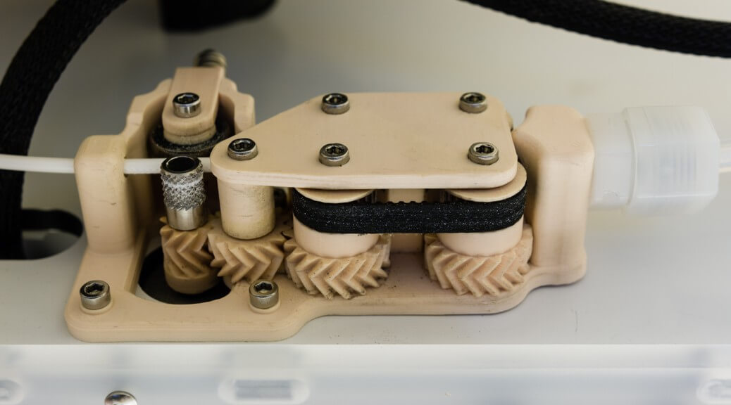
Extruder in Action
Extruder Revision E (Alternative)
This revision is an alternative design to revision E which replaces the helical gears with herringbone gears. The use of herringbone gears provides smoother meshing, no side-thrust, and possibly reduced friction between parts. The downside is the increased size of the gears, doubling them from 4mm to 8mm with an addition 5mm required as the hobbed gear needs to be flipped (the motor shaft is too short). The profile of this design is 9mm taller than the original, possibly leading to reliability issues down the road. I have no plans on printing/testing this particular design so if anyone does, do let me know how it performs.
")
")
")
")
")
Extruder Revision F
Revision F design filesParts have been designed to be 0.3mm larger. This should be taken taken into account when printing.
After ~300 or so hours of printing with revision E of the design, I found a few small issues with the design that could potentially cause problems with certain prints. The most pressing issue lies in the intermediate gear that sits in-between the motor gear and the belt gears. The problem was that this gear would tilt slightly depending on the direction that its rotating in. Because of this, when the stepper motor changes directions, the first ~2-6 steps of the motor would turn the hobbed gear but the belts would stay stationary. The filament is compressed between the hobbed gear and the belts during this small period of time instead of feeding into the hot-end. This can be fixed by tightening the screw that holds the gear between the top and bottom plates, but it was a balancing act as tightening it too much resulted in the stepper motor skipping from the increased friction. This is an unavoidable issue in helical gear designs due to the side-thrust resulting from the angled teeth. To fix this problem, I decided to switch to the alternate design that utilizes herringbone gears.
The use of herringbone gears also has another benefit: the increased contact area between the gears. In my prints with revision E of the design, I’ve had one instance where some of the teeth on the motor gear actually broke from the torque. The possibility of this happening again should be eliminated (or at least heavily reduced) with this revision. It’s a good idea to have spare parts on hand in case this happens.
Another issue that I encountered was the bowden tube would pop out from the push-to-connect fitting that came with the original filament extruder. I got tired of having to constantly trim off the ends of the bowden tube whenever I re-installed it so I replaced the push-to-connect fitting with a compression fitting instead. So far this seems to work pretty well, with no movement of the tube during retractions.
Update 12/26/2014:
After a few hundred more hours with this revision, there is a noticeable deterioration with the neoprene belt that is in contact with the rough side of the filament (see pictures below). The rubber bits from the belt rub off and attach themselves to the filament which then affects the quality of the resulting print. As a temporary fix, I replaced the deteriorating belt with an urethane belt of much higher durability. This seems to work fairly well as the urethane belt serves to press the filament against the neoprene belt on the opposite side without wearing down. The friction from the neoprene belt combined with the herringbone gearing system works well in controlling the filament.
Assembly Notes:
- One bearing must be used on the intermediate gear
- Assemble all pieces before attaching to the printer
- Nuts can be easily inserted by pulling it in with a screw on the other side
- ABS is recommended for the gear that attaches to the motor
- You will probably need to hammer in this gear as it’s designed to fit tightly
- PLA deforms too much under stress for this particular part
- Make sure the outer coating on the belts are removed with rubbing alcohol
- Test them by rubbing them against some filament, there should be a tight grip
- Don’t overtighten the screws
- If the gears are hard to turn by hand once assembled, try loosening the screws
- I would recommend printing everything with 100% infill
- If there is ANY backlash between the gears, you WILL get underextrusion issues
- Print the gears slower to allow for increased material expansion (wider parts)
- The belts should fit with little to no extra slack when assembled
- If there is any amount of slack, the parts are smaller than designed
- Print extras for every part! The gears WILL likely break at some point
- The hobbed gear will not end up being flush with the end of the motor shaft
- Insert it in just enough for the mounting screw to get a good hold (rev. E only)
- The screw for the intermediate gear should be well tightened (rev. E only)
- Any axial movement of this gear will affect extrusion quality
- Print the motor gear slowly (<10mm/s) otherwise it may not get printed properly
- The belts WILL wear out. Have some extra replacement belts on hand
Bill of Material (Rev. F):
- 1x 4in Neoprene Belt
- 1x 4in Urethane Belt
- 1x Nylon Compression Tube Fitting
- 6x M3 25mm Screw
- 5x M3 16mm Screws
- 6x M3 1.6mm Low-Profile Nuts
- 5x M3 Washers
- 5x 3x8x4mm Bearings (only one is required, others are optional for smoother performance)
- 1x 6x6x3mm Metal Spacer (optional but prevents wear on the inlet)
- 1x 8x5x3mm Metal Bearing (comes with original extruder)
- 1x 16x8mm Spring (comes with original extruder)
Print settings for this revision on PLA (ABS):
- Nozzle Diameter: 0.30mm (0.3mm/0.4mm)
- Layer Height: 0.1mm (0.1mm)
- Extrusion Multiplier: 1.00 (1.00/1.10)
- Retraction Distance: 5mm (5mm)
- Retraction Vertical Lift: 0.4mm (0.4mm)
- Retraction Speed: 100mm/s (100mm/s)
- Nozzle Temperature: 210C (250C)
- Bed Temperature: 60C (90C)
- Fan: 100% @ layer 10 (100% @ layer 12)
- Print Speed: 10-100mm/s (10-100mm/s)


Extruder Revision G
While revision F of the design works pretty damn well, there are still a few odd issues that I need to sort out. One of the issues I encountered after hundreds of hours of printing is that the rubber belts seem to be rubbing off on the filament and sticking to the roughened surface. I haven’t narrowed down the exact cause of the problem, but I suspect it has something to do with belt tension, extrusion friction, gear ratio, and/or retraction speed and compression of the filament being extruded.
Another issue encountered was that the increased friction of the system causes the stepper motor to occasionally skip after a certain amount of filament was extruded. The friction between the filament and bowden system seems to increase over time due to the ridges generated from the hobbed wheel. A temporary solution that I found was to increase the hotend temperature by 10C (240C->250C for ABS), reducing the end friction just enough to prevent the motor from skipping. This slight decrease in friction also seems to have partially solved the first issue as well.
For the next revision, I’m thinking about redesigning the extruder to use rubber wheels rather than belts for ensuring extrusion reliability. Adding in a self-cleaning feature with soft deburring brushes that rotate in the opposite direction to the wheels would also help long term reliability when using soft filaments such as ABS. As usual, I’ll be updating this post with the new design when I finish it.
Update 8/26/2015:
As I’ve stopped development on all my 3D printing related projects, here’s a link to what I would consider the logical followup iteration of my original design. This design utilizes the rubber wheels that I mentioned in my last revision as an alternative to rubber belts. The additions are all 3D printed, with the author even using Ninjaflex filament for the rubber slip-ons.