Design files for this project can be found here
1/21/2017 – Update to the alignment blocks
One of the issues with the Roland MDX-540 is that it’s surprisingly difficult to mount stock for milling when not using the vise in the rotary unit. The old fixturing table consisted of an MDF sheet with a few holes drilled in it to allow it to be attached to the aluminum extrusions. Removal of the table was required to mount anything, so it was nearly impossible to mount stock with any sort of accuracy onto the table. My fix for this was to redesign and remake the fixturing table out of aluminum together with some custom clamps and alignment blocks to allow for the precise positioning of stock onto the table.


My first attempt at an improved fixturing table was to remake the table in MDF with 1/4″-20 nuts for mounting screws. In addition to this, an array of ‘+’ shaped cutouts was milled out in the MDF to hold nuts that could slide within the slots. A sheet of acrylic with laser cut holes was attached to the top half to hold the nuts in place and to provide a smoother surface for better double sided tape adhesion. The design worked but we quickly hit a number of problems. One of the issues was with the material used: if someone over-torqued the mounting screws attached to one of the fixed nuts, the MDF would either strip (trapping the screw) or compress enough to permanently deform (messing up the table’s flatness). Over-tightening screws attached to the sliding nuts often cracked the acrylic sheet, thus damaging the structural integrity and surface flatness of the table.

")


Table Dimensions

Fixturing Clamps and Alignment Blocks
The new table design makes it easy to mount stock with pre-drilled mounting holes, but I often work with stock that is too thin or small to be bolted down directly to the table. To secure this type of stock, I designed and milled out custom clamps to securely hold stock against the table. Height adjustment for the clamps is done via a screw on one end that was modified to have a flat head for distributing pressure evenly on the acrylic. A slot in the middle then allows the clamp to be bolted down to one of the mounting holes, thereby securing any stock up to 1″ in thickness to the table.
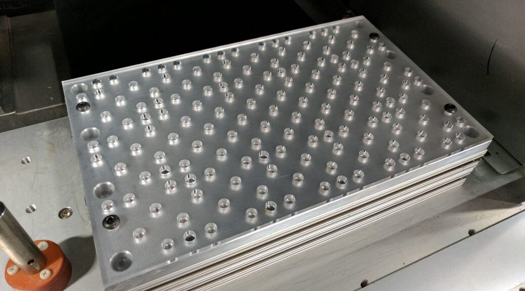
Another feature that I wanted was a way to accurately position the stock on the table such that a given corner of the stock would have a known constant value in machine coordinates. To make things easy, the top left corner of the aluminum table was fixed at (80, 378) when the table was mounted in the machine. All holes, both alignment and threaded holes, were milled relative to this corner.
Alignment Rev. A
Alignment holes were milled out to be 0.25″ in diameter for the precision steel dowels. Corresponding alignment block were then milled out on the machine with holes for the steel dowels at each end. This design allows the alignment blocks to be easily removable while still holding an accuracy of less than 0.001″. In theory this accuracy should be good enough to allow me to flip a part and machine the other side without a lip resulting when milling the same X-Z or Y-Z plane.


")
")
")
Alignment Rev. B
There were a few problems with rev. A in that some of the alignment holes had a bit more slack than I would’ve liked. Furthermore, tolerances on the holes milled in the blocks themselves as well as the outer dimensions of the block added enough that the accuracy was off by >0.001″. As such, I decided to approach it with a different fashion: to align stock to the table using only 8mm steel dowels. Pretty good results so far with very little play once the dowels are inserted in. The bigger source of inaccuracy now is in the homing precision..
")
")
")
")
")