The latest code base for this project can be found hereVideo and pictures are at the bottom of the post!
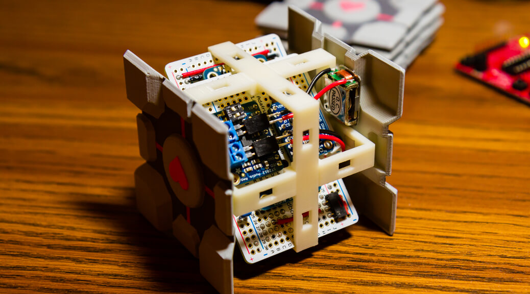
So I wanted to give a friend the 3D printed companion cube as a birthday gift, but I figured that just the cube by itself would be rather boring. Instead, why not add some audio functionality to the cube to make it a bit more impressive? And so I did. As I came up with this project idea only three weeks before the deadline, I was in a bit of a rush to get things working. As such, designing and ordering a custom PCB was out of the question. Instead of using a custom PCB, I came up with a stacking design using Adafruit’s perma-protoboards that would fit inside of the cube’s frame while still allowing enough real estate for all the components. As the frame was slightly smaller than the protoboards, I had to file the edges of the protoboards down a bit to get them to fit. The upside to this design was that I was able to achieve an extremely snug fit that should be pretty resistant to drops.


Features
The functionality of the cube is about as basic as it gets. The main feature of this project was to make it so that the cube would play a random audio file from the game Portal whenever the cube was moved or tapped. Other than the main feature, I also implemented a few extra design choices to make it more flexible. For example, I wired in a USB lithium-polymer battery charger directly into the cube so that the charging circuitry would be part of the cube. The lithium-polymer battery is removable as well, so the user could replace it with a larger capacity battery if desired. Battery life is pretty good with the included 400 mAh battery, lasting an estimated 37 days in standby with 8 hours of audio playback time.
There is also an audio gain switch on the amplifier that allows the user to select an amplification of 6/12/18/24 dB in the event that the sounds are too quiet. Setting the gain too high though (>18 dB) will result in sound distortion. The audio tracks are located on the microSD card, and the cube automatically determines the number of tracks available to play on startup. The only non-flexible part of this design (due to the lack of time) is that the tracks have to be incrementally numbered track1.mp3 to trackXXX.mp3 so that the cube can easily select the file to play.
Components and Functionality
After ensuring that I would be able to fit the protoboards into the frame, I started putting together the individual parts for achieving the functionality that I wanted. To achieve this functionality, I used the VS1053 audio decoder along with the TS2012 amplifier for the audio playback, and the ADXL345 accelerometer chip for the movement detection. I decided to use the MSP430G2553 as my microcontroller of choice. The MSP430 was chosen for two reasons: I wanted to minimize power consumption of this project (since it will be battery powered) and I wanted to get some practice programming for the MSP430 architecture.
The VS1053 audio decoder is pretty simple to use. You simply read in an MP3/WAV/MIDI/OGG file from a microSD card and send the file contents to this chip. It automatically decodes the audio file and outputs it at the correct bitrate. The VS1053 breakout board even includes a microSD card breakout to make things easy. Implementing the library to read in files from an SD card however, was not quite as easy. Rather than implementing my own SD card and FAT12/16 file system library, I used a library provided by TI for accessing SD cards. I had to modify a few things, but the majority of the library was untouched. For the file system, I found the Petit FAT library that implemented the details of FAT12/16/32. As with the SD card library, most of this code was untouched except for the SPI/SD card read/write functions.
The audio output from the VS1053 decoder is wired to the TS1012 class D amplifier which is capable of driving 8 ohm speakers at 1.7 watts. For the speakers, I initially tried using some small speakers that I had lying around, but I found out that when the cube was closed, the sound became too muffled. To remedy this, I decided to use these small surface transducers from Sparkfun. By attaching the transducers to the walls of the cube, I was able to achieve decent quality sound when all the panels were attached. The transducers themselves are attached using some strong epoxy, which I’m hoping will be durable enough to withstand the vibrations.
The movement detection was implemented through the ADXL345 accelerometer. This accelerometer is nice in that it not only operates on very low power, but also provides an interrupt output when it detects acceleration past a given threshold. By wiring this interrupt to the MSP430, I could put all the chips involved in this project into a low-power state while waiting for the interrupt to trigger.
Originally, I wanted to use a chip from the MSP430G2XX1 family, which has the lowest pin count of 14 (in a DIP package) and thus offering more room on the protoboards for other components. The G2XX1 family however, only goes up to 2 kB ROM and 128 bytes of RAM. Once I started porting the SD/FAT libraries to the G2231, I quickly found that I was running out of both ROM and RAM. Given no choice but to go up a tier, I tried using the G2XX2 family which has a pin count of 20 and offered up to 8 kB ROM and 256 bytes of RAM. While 8 kB of ROM was (barely) enough, having only 256 bytes of RAM caused stack overflows at certain points in the FAT library. Going up yet another tier, the G2XX3 family had just enough resources to fully implement everything at 20 pins, 16 kB of ROM, and 512 bytes of RAM.
Battery Life
One of the more important features of this project is its low power consumption when its in standby mode. As I was limited on space, I had to power this cube through a 400 mAh lithium-polymer battery. Thus, minimizing power was a high priority and I wanted to get the idle current consumption to < 1mA when in standby. According to the datasheets, the MSP430G2553 chip draws ~4.2 mA when active at 16 MHz and ~50 uA when in LPM1. The VS1012 decoder draws anywhere from ~11 mA to ~40 mA when active, and down to ~12 uA when in shutdown mode. The TS1012 amplifier will draw a minimum of ~5 mA when active and < 1 uA when in shutdown mode. Finally the ADXL345 accelerometer draws a minimum of ~23 uA when active and < 1 uA when in standby. Totalled up, the chips should draw < 100 uA when in sleep (except the accelerometer which is active).
Unfortunately however, the voltage regulators have some quiescent current that needs to be taken into account as well. To minimize leakage current, I removed the voltage regulators on all the breakout boards from Adafruit. Then I added two regulators: a TPS77733 3.3v regulator and a MIC2941AWT adjustable regulator. The TPS77733 regulator has a quiescent current of ~85 uA and the MIC2941AWT regulator at 1.8v has a quiescent current of ~60 uA. Combined, both regulators draw ~145 uA of current regardless of the load.
Totaled together, all the devices combined should draw < 250 uA. With a 400 mAh battery, this comes out to be around 66 days of battery life, which is pretty good. When the sleep current was measured however, the actual consumption came out to be ~435 uA which is quite a bit higher. Even with this higher consumption, the estimated battery life is still 37 days which is acceptable. If I had more time, I would like to go back and figure out where this extra current consumption is coming from. I’m thinking it may be from some of the pull-up/down resistors on some of the breakout boards. When playing back audio, the cube draws an average of ~50 mA which results in about 8 hours of actual audio playback time.
Conclusion
Overall, I’m pretty satisfied with the results achieved over a week and a half of work. The desired functionality was achieved, albit with a bit less battery life than what I originally desired. For a project like this, a video is worth far more than a writeup, so here’s a video of me demoing the functionality of the cube, along with a teardown and reassembly of the entire project:


